Fig. 8.1
An x-ray of a patient, showing the defect after debridement for osteomyelitis
Fig. 8.2
An MRI study of a patient displaying the extent of osteomyelitis
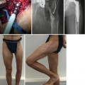
Bone defects and/or shortening after removal of an infected tumor prosthesis (Figs. 8.3 and 8.4)
Fig. 8.3
An x-ray of a patient displaying an infected tumor prosthesis, AP view
Fig. 8.4
An x-ray of the same patient, lateral view
8.2.2 Examination
Physical examinations should include the following:
Bilateral ROM of the hip, knee, and ankle joints.
Measurement of the actual (distance between the anterior superior iliac spine (ASIS) and the medial malleolus) and the apparent limb-length discrepancy (LLD: distance between the umbilicus and the medial malleolus).
Determination of the number of 1-cm blocks required under the shortened extremity to provide a level pelvis.
Photographic documentation of each patient, both initially and at the end of the treatment.
Assessment of potential joint contractures.
Careful evaluation and documentation of neurologic and vascular status.
For cases with a history of thromboembolism, a Doppler ultrasound examination should be performed, and prophylaxis should be initiated.
Evaluation of nutritional status (albumin, albumin/globulin ratio, and lymphocyte count).
8.2.3 Imaging Studies
Plain x-rays in both planes (true AP and lateral).
Orthoroentgenogram in both planes, according to the following guidelines:
The knee should be in maximum extension, especially in the lateral view.
1-cm blocks should be used to level the pelvis in the AP view (Fig. 8.5).
Fig. 8.5
Bone blocks used to determine the extent of shortening
Scaled AP and lateral x-rays of the affected bone segment are necessary to obtain the size and the diameter of the IM nail and to determine the numbers and levels of the osteotomy(ies).
A computed tomography (CT) scan (to check for sequestra) (Fig. 8.6).
Fig. 8.6
A CT scan of a patient, displaying a sequestrum
Magnetic resonance imaging (MRI) to assess the following:
The extent of bone infection and abscess formation (MRI may reveal a well-defined rim with a high signal intensity that surrounds the focus of active disease, which represents the so-called rim sign) (Fig. 8.7) (Dabov 2008)
Fig. 8.7
An MRI of a patient showing the extent of the abscess and the active disease
The margins of bone resection
Determination of the vascular status of the affected extremity using Doppler ultrasound (the contralateral side should also be checked if the free flap will be obtained from this side).
Conventional angiography should be included when there is suspicion following the Doppler examination (Fig. 8.8).
Fig. 8.8
Conventional angiography from a patient
Tc-99- and indium-111-labeled leukocyte radionuclide scans should be performed to identify any foci of distant infection (or dead bone).
Fistulography should be applied to track the infection from the inside of the tissue to the surface (Fig. 8.9).
Fig. 8.9
Fistulography of a patient
8.2.4 Preoperative Planning
All data obtained from the clinical examination and imaging studies should be carefully evaluated.
A deformity analysis should be performed, according to the deformity planning guidelines of Paley and Tetsworth (1992).
Determination of the level(s) of the osteotomy(ies) and the margins of resection.
If the defect is at the distal femoral metaphysis, retrograde IM nail insertion should be performed through the intercondylar notch.
If there is additional shortening, the IM nail should be longer than the femur. The length of the nail outside of the femur should be as long as the planned amount of lengthening (Figs. 8.10a, b).
Fig. 8.10
An x-ray of a patient where the IM nail was left in contact with the bone (a). The nail length was chosen to fit the original length of the bone, which was determined when the lengthening was complete (b)
If there is only a mid-diaphyseal defect without shortening, an antegrade IM nail may be chosen.
The diameter and size of the IM nail should be determined based on the scaled AP and lateral x-rays of the affected bone segment(s).
Paper tracing should be performed to simulate the surgery and to determine the provisional and final position of the bone segment (Fig. 8.11), according to the following factors:
Fig. 8.11
Paper tracing to simulate the surgery
The localization of the extra custom-made hole(s) on the IM nail (Fig. 8.12).
Fig. 8.12
The locations of extra custom-made hole(s) on the IM nail are determined prior to surgery
The location and number of interference screws (poller) should be determined in a manner that increases the stability of the reconstruction (Fig. 8.13).
Fig. 8.13
The location and number of poller screws are determined prior to surgery
The incision at the entry point of the IM nail and the osteotomy levels should be mapped out.
8.2.5 Equipment
First Stage
1.
Radiolucent table
2.
Radiolucent knee support or a rolled, sterile towel
3.
Large-field fluoroscopy
4.
Flexible intramedullary reaming system
5.
Antibiotic-impregnated bone cement or bone cement with appropriate heat-stable antibiotics (gentamicin, tobramycin, teicoplanin, vancomycin, etc.)
6.
Steinmann pins of various sizes (for creating antibiotic-impregnated cement rods)
Second Stage
1.
Radiolucent table
2.
Radiolucent knee support or a rolled, sterile towel
3.
Large-field fluoroscopy
4.
6-mm conical hydroxyapatite-coated Schanz screws
5.
Unilateral external fixator (EBI Monorail System or Orthofix LRS)
6.
Flexible intramedullary reaming system
7.
1.8-mm Kirschner wires (bayonet type)
8.
3.5-mm cannulated drill bits
9.
Intramedullary nail (the authors prefer Ortopro 4G Nails from Istanbul, Turkey)
8.2.6 Positioning
The patient is placed in the supine position on the radiolucent table, and the affected hip should be slightly elevated using a silicone bag under the buttock to provide a lateral view (Fig. 8.14).
Fig. 8.14
The positioning of the lower extremity, which enables visualization in both planes (AP and lateral) with the C-arm
Fluoroscopic images are then acquired from the hip to the ankle joint in both planes prior to the sterile preparation.
Sterile preparation should be used prior to draping the entire lower extremity beginning at the ASIS.
8.2.7 Surgical Technique
First Stage
For the exposure/incision:
Methylene blue should be injected through the fistula to dye the sinus and its tract.
The entire sinus tract should be excised with the fistula (fish-mouth incision) (Fig. 8.15).
Fig. 8.15
A fish-mouth incision is used to completely remove the sinus tract
If there is no fistula, then a transverse incision is preferred, especially for cases of tibial osteomyelitis. The transverse incision helps to prevent soft tissue buckling due to the extremity shortening induced by the bone excision (Fig. 8.16).
Fig. 8.16
A transverse incision is used to avoid buckling after shortening due to bone excision
A wide resection margin is preferred (>7 mm) over marginal excision, as it prevents recurrence.
Hardware is removed (remove all nails, plate, cerclage wires, screws, etc.) (Fig. 8.17).
Fig. 8.17
All hardware should be removed
The dead bone can be resected through debridement and the use of multiple drill holes and the osteotomy technique (to prevent heat necrosis, do not use a power saw) (Fig. 8.18).
Fig. 8.18
The dead bone is resected via the multiple drill-hole and osteotomy techniques
If the defect is too large to be closed primarily, then rotational local or free myocutaneous flaps (i.e., latissimus dorsi transfer) may be used (Fig. 8.19).
Fig. 8.19
Free flaps are utilized as needed
All sequestra, purulent material, and scarred necrotic soft tissue should be removed.
Cortical bleeding, denoted by the Paprika sign, is accepted as an indication that the bone tissue is vital (Fig. 8.20).
Fig. 8.20
The Paprika sign reveals the existence of vital bone tissue
Debridement proceeds until bleeding, living tissue is observed at the resection margins to ensure that all foci of infection are removed (Patzakis and Zalavras 2005; Tetsworth and Cierny 1999).Related posts:
 Distraction Arthroplasty for Ankle Osteoarthritis
 Hybrid Lengthening Techniques: Lengthening and Then Nailing (LATN) and Lengthening and Then Plating (LAP)
 Congenital Pseudarthrosis of the Tibia: Redefined (Congenital Crural Segmental Dysplasia)
 Lengthening over Nails (LON): Femur and Tibia
 Joint Contracture Management with External Fixators
 Pelvic Support Osteotomy (PSO): Indications, Limits and Complications

Stay updated, free articles. Join our Telegram channel

Full access? Get Clinical Tree


