Fig. 3.1
A patient’s preoperative photographic documentation displaying long bowing deformities in the lower extremities (a, front view; b, side view)
However, Ilizarov-type external fixators have disadvantages, such as pin-track infections, discomfort, and bulkiness (Bilen et al. 2010). Internal fixation provides better patient comfort but requires substantial technical skill and expertise (Paley et al. 1997a, b).
Two techniques, fixator-assisted nailing and lengthening over a nail, have been combined for the treatment of cases of femoral deformity associated with limb-length discrepancy (Bilen et al. 2010; Kocaoglu et al. 2009; Paley and Herzenberg 2002).
The standard treatment for this group of patients has been external fixation alone. With the combined technique, we capitalized on the advantages of both individual techniques (Bilen et al. 2010; Kocaoglu et al. 2009; Paley and Herzenberg 2002). However, the combination of fixator-assisted acute deformity correction and consecutive lengthening over an intramedullary nail requires careful analysis of the deformity and extensive preoperative preparation (Paley and Herzenberg 2002; Paley and Tetsworth 1992). The surgeon must be familiar with both intramedullary nailing and external fixation techniques, as the two techniques both have steep learning curves (Eralp et al. 2004).
In this chapter, we describe the technical details and tips and tricks.
3.2 Femoral FAN-LON
3.2.1 Indications
3.2.1.1 Congenital Deformities
PFFD Paley type 1 (congenital short femur with distal valgus deformity)
Short stature with deformities due to bone dysplasias (achondroplasia, hypochondroplasia, spondyloepiphyseal dysplasia, multiple epiphyseal dysplasia, etc.)
Hemihypertrophy (Beckwith-Wiedemann syndrome)
3.2.1.2 Acquired Deformities
Posttraumatic defect nonunions associated with deformities (Paley B3) (Paley et al. 1989)
Deformity with LLD due to posttraumatic or postinfectious epiphyseal damage
Postinfectious defect stage 1 nonunions created by the surgeon (Kocaoglu et al. 2006)
LLDs and deformities due to bone tumors (including postsurgical iatrogenic defects and sequelae)
Multi-apical deformities and constitutional short stature due to metabolic bone disease (rickets, hypophosphatemic rickets, etc.)
3.2.2 Examination
The physical examination should include the following:
ROM of the hip, knee, and ankle joints bilaterally.
Measurement of the real (distance between the anterior superior iliac spine [ASIS] and medial malleolus) and apparent LLD (distance between the umbilicus and medial malleolus).
Determination of the number of blocks (each 1 cm) under the shortened extremity to provide a level pelvis (Fig. 3.2a, b).
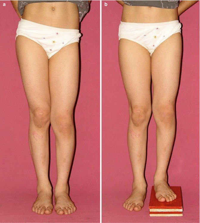
Fig. 3.2
A patient with limb length discrepancy displays pelvic asymmetry (a), which diminishes using blocks under the shortened extremity (b)
Photographic documentation of the patient, initially and at the end of the treatment.
Evaluation for joint contractures.
Careful evaluation of neurologic and vascular status.
In the presence of a history of thromboembolism, Doppler ultrasound examination should be performed, and prophylaxis should be started.
3.2.3 Imaging Studies
Plain x-rays in both planes (true AP and lateral)
Orthoroentgenogram in both planes (Fig. 3.3a, b)
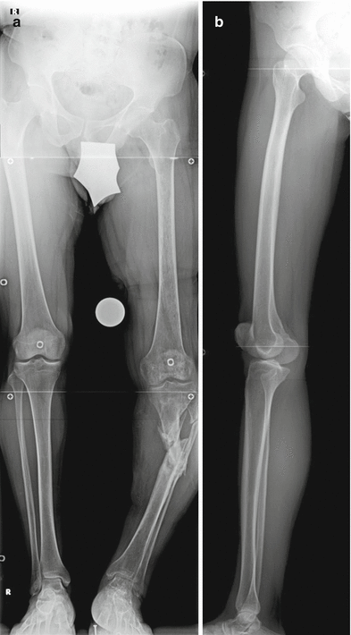
Fig. 3.3
Preoperative orthoroentgenograms, AP (a) and lateral (b)
The knee should be in maximum extension, especially in the lateral view.
One-centimeter blocks should be used to level the pelvis in the AP view (Fig. 3.4).
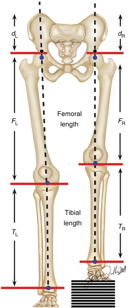
Fig. 3.4
A drawing displaying one-centimeter blocks under the shortened extremity to provide a level pelvis
Scaled AP and lateral x-rays of the affected bone segment are necessary to obtain the size and the diameter of the IM nail and to determine the numbers and levels of the osteotomy/osteotomies.
A computed tomography (CT) scan or even a magnetic resonance imaging (MRI) study provides useful information in cases of articular pathologies (Fig. 3.5).
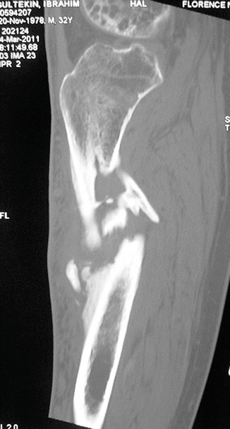
Fig. 3.5
A computerized scan (CT) displaying a nonunion of the tibia associated with shortening
3.2.4 Preoperative Planning
All data obtained via clinical examination and imaging studies should be carefully evaluated.
The deformity should be analyzed according to deformity planning guidelines outlined by Paley (Paley and Tetsworth 1992) (Fig. 3.6).
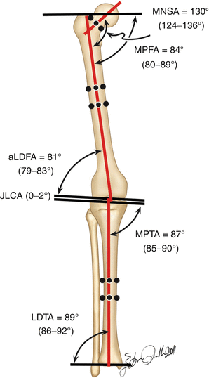
Fig. 3.6
Normal values of deformity planning analysis of the lower extremities
The level(s) of the osteotomy/osteotomies in the affected bone segment should be determined according to anatomic axis planning (Paley and Herzenberg 2002).
If there is a deformity at the distal femoral metaphysis, retrograde IM nail insertion should be performed through the intercondylar notch.
If there is an additional proximal metaphyseal deformity, then the length of the IM nail chosen should be longer than the femur. The amount of the nail length outside of the femur should be as long as the planned amount of the lengthening (Figs. 3.7a, b and 3.8).
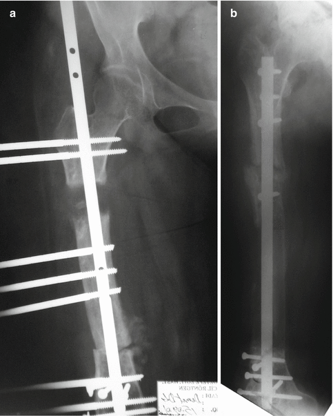
Fig. 3.7
The intramedullary nail is longer than the femur and lies outside of the bone proximally (a). At the end of lengthening, the entire nail lies within the bone and is locked statically at the proximal femur (b)
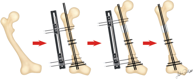
Fig. 3.8
Schematic drawing of a femoral FAN-LON procedure. Initially the IM nail is longer than the bone; however, it lies entirely within the bone at the end of lengthening
If there is only a proximal metaphyseal deformity of the femur, then an antegrade IM nail can be chosen.
The diameter and the size of the IM nail should be determined based on the scaled AP and lateral x-rays of the affected bone segment(s) (Fig. 3.9a, b).
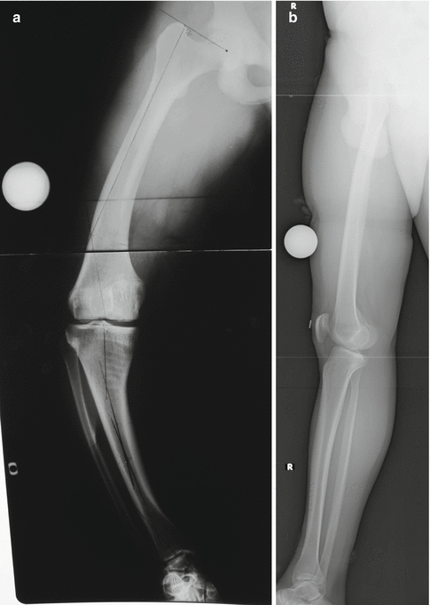
Fig. 3.9
On AP (a) and lateral (b) x-rays, marked with a 2.5-cm radius circle, the length and the size of the IM nail can be determined
Paper tracing should be performed to simulate the surgery and to determine the provisional final position of the bone segment(s) (Fig. 3.10).
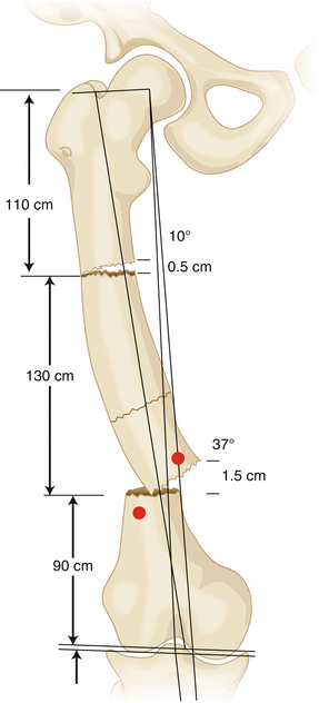
Fig. 3.10
Paper tracing to stimulate a femoral procedure
The extra custom-made hole(s) on the IM nail should be determined (Fig. 3.11).
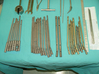
Fig. 3.11
A set of IM nails of different types with custom-made extra holes
The location and number of the interference (poller) screws should be assigned to increase the stability of the reconstruction (Fig. 3.12) (Krettek et al. 1999a, b; Seligson 2000).
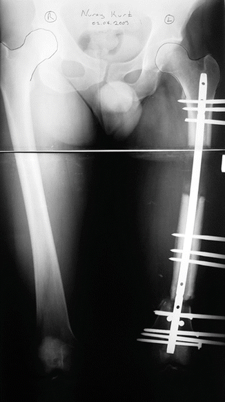
Fig. 3.12
Two poller screws distally provide extra stability around the IM nail distally at the metaphyseal level
The incision of the entry point of the IM nail and the osteotomy levels should be determined.
3.2.5 Equipment
1.
Radiolucent table
2.
Radiolucent knee support or rolled sterile towel
3.
Large-field fluoroscopy
4.
Six-millimeter conical hydroxyapatite-coated Schanz screws
5.
Unilateral external fixator (Orthofix LRS, Bussolengo, Italy, or EBI Monorail Fixation System, Biomet, Parsippany, NJ, USA) (Fig. 3.13)
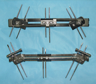

Fig. 3.13
Unilateral external fixators to be used in FAN-LON cases: Orthofix LRS, Bussolengo, Italy (above), and EBI Monorail Fixation System, Biomet, Parsippany, NJ, USA (below)
6.
Flexible intramedullary reaming system
7.
Kirschner wires (bayonet tip), 1.8 mm
8.
Cannulated drill bits, 3.5 mm
9.
Intramedullary nail (the authors prefer Ortopro Retrograde 4G Nails, Istanbul, Turkey) (Fig. 3.11)
3.2.6 Positioning
The patient is placed supine on the radiolucent table with the affected hip slightly elevated, using a silicone bag under the buttock to facilitate the lateral view (Fig. 3.14).
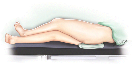
Fig. 3.14
Positioning of the lower extremity on a radiolucent table, with a silicon bag underneath the buttock to facilitate lateral view
The region from the hip to the ankle joint is checked by fluoroscopy in both planes before sterile preparation.
The entire lower extremity is sterile prepared and draped, starting from the ASIS.
Prophylactic antibiotherapy is initiated (first-generation cephalosporin, cephamezine 4 × 1 g IV for 3 days).
3.2.7 Surgical Technique
3.2.7.1 Exposure/Incision
Osteotomies in the long bones can be executed percutaneously through limited incisions, by either the Gigli saw technique or the multiple drill hole technique (Paley and Tetsworth 1991). The placement of the intramedullary nail also can be performed through a 2-cm transverse incision over the patellar ligament (Fig. 3.15 left).
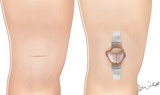

Fig. 3.15
A transverse skin incision (left) is used over the patellar ligament, then the paratenon and the (red) dotted line depicts the longitudinal split of the patellar ligament (right)
The reason behind the choice for a transverse incision is that it leads to less scarring, thus making it cosmetically more acceptable (Fig. 3.16). However, the paratenon and the patellar ligament are split longitudinally (Fig. 3.15 right). Before the acute correction of valgus deformities around the knee of more than 20°, prophylactic peroneal nerve release must be performed (Paley 1990) (Fig. 3.17).
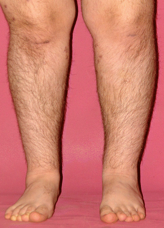
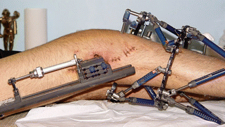

Fig. 3.16
A much better cosmetic healing can be obtained using transverse incision

Fig. 3.17
A patient’s photograph who underwent prophylactic peroneal release
Schanz screws are placed perpendicular to the anatomic axis of each segment, proximally and distally (and at the middle segment, when present) with the cannulated drill technique (Figs. 3.18 and 3.19) (Paley and Herzenberg 2002).
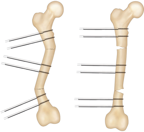
Fig. 3.18
Correction of a femoral deformity using perpendicular (to the anatomic axis of each segment) Schanz screws
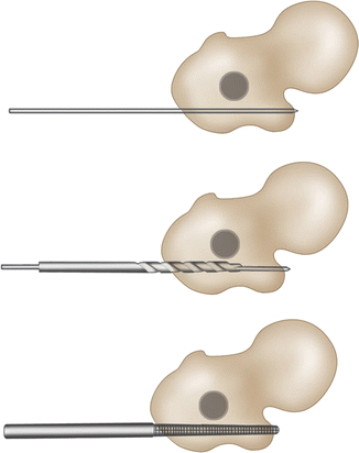
Fig. 3.19
Schematic drawing depicting the cannulated drill technique for Schanz screw placement to the posterior aspect of the proximal femur. There should be at least 1-mm space between the screw and the IM nail
The Schanz screws should be placed posteriorly to leave enough space for the IM nail (Fig. 3.20).
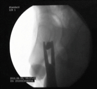
Fig. 3.20
Enough space should be left for the IM nail at the posterior aspect of the proximal femur
There should be at least 1 mm of space between the IM nail and the Schanz screws to avoid spreading any pin-track infection into the medullary space (Fig. 3.21).
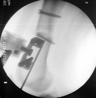
Fig. 3.21
Enough space should be left for the IM nail at the posterior aspect of the distal femur
Schanz screws are placed parallel to the axial plane of each fragment. Thus, once the Schanz screws are secured to the external fixator following the osteotomy/osteotomies, the rotational deformities have been corrected (Fig. 3.22a, b).
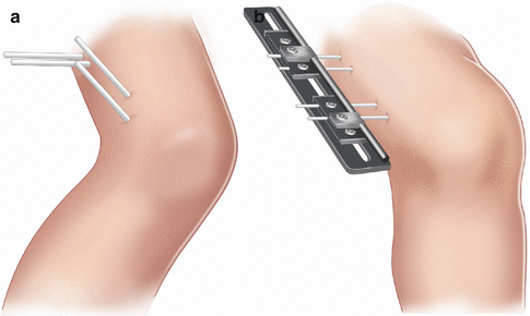
Fig. 3.22
Correction of a rotational deformity of the femur can be performed by applying the Schanz screws parallel to the axial plane of each fragment (a). Following the osteotomy, once the Schanz screws are brought in line and the external fixator is mounted, the rotational correction is obtained accordingly (b)
To correct sagittal plane deformities, the Schanz screws need to be placed parallel to the sagittal plane axis of each fragment (Figs. 3.23a, b).
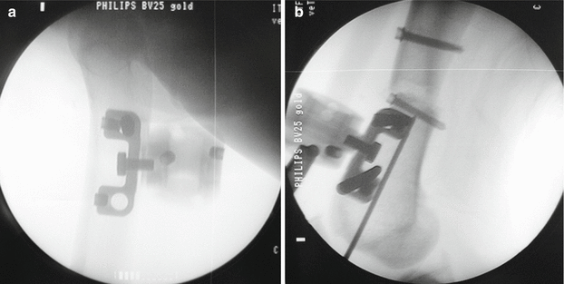
Fig. 3.23
Sagittal plane deformities can be corrected by placement of the Schanz screws parallel to the sagittal plane axis of each fragment proximally (a) and distally (b)
Using 3.5-mm drill bits, multiple drill holes are created percutaneously at the osteotomy level(s).
An obligatory translation is necessary at the osteotomy level, especially in the metaphyseal area if the center of rotation of angulation (CORA) is at a different level (Fig. 3.24).
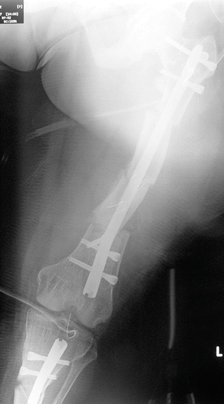
Fig. 3.24
X-ray of a patient displaying an obligatory translation due to the osteotomy (because the level of the osteotomy is different than the CORA)
The maximum contact at the translated osteotomy level can be obtained with a dome-shaped osteotomy (Fig. 3.25).
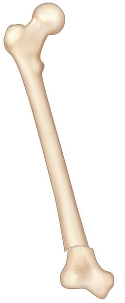
Fig. 3.25
Schematic drawing of a dome-shaped osteotomy providing a large contact area
The creation of a dome osteotomy is technically demanding, whereas a transverse-shaped osteotomy is easier to create; however, after translation and angulation, the contact between the two fragments remains only at the edge of the fragment (Fig. 3.26).
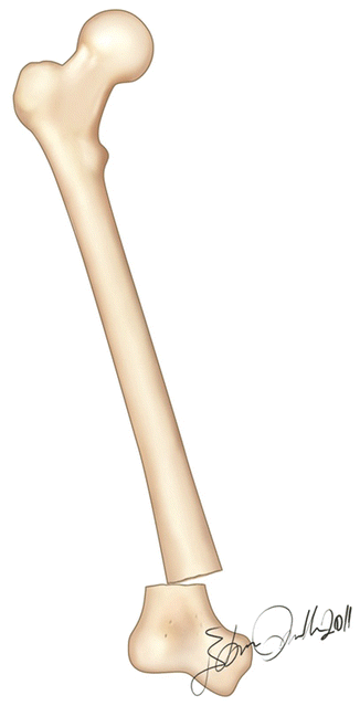
Fig. 3.26
Schematic drawing of a transverse osteotomy leading to a point contact between the fragments
The level of lengthening osteotomy and the length of the IM nail are chosen to ensure that at least 8 cm of the nail lies above the distraction gap at the end of the lengthening procedure (Fig. 3.27) (Paley et al. 1997a, b).
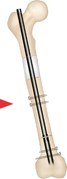
Fig. 3.27
Schematic drawing of a femoral FAN-LON procedure at the end of the treatment. The length of the IM nail must extend at least 8 cm above to the level of the distraction gap
The deformity is corrected acutely using an LRS-type external fixator (Orthofix, Bussolengo, Italy) or an EBI Monorail Fixation System (Biomet, Parsippany, NJ, USA) (Fig. 3.28).
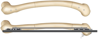
Fig. 3.28
Correction of a sagittal deformity using an external fixator. The Schanz screws are placed parallel to the sagittal axis of each fragment
Stay updated, free articles. Join our Telegram channel

Full access? Get Clinical Tree


