Abstract
This chapter covers the history and role of radiography, computed tomography (CT), and magnetic resonance imaging (MRI) in the evaluation of the craniofacial skeleton in the setting of blunt and penetrating trauma. The basic craniofacial anatomy is reviewed in all imaging modalities, including a video demonstrating a systematic review of a craniofacial CT. Both common and uncommon craniofacial injuries as well as their potential complications are discussed. The advantages and disadvantages of each imaging modality in both the pre- and postoperative period are also discussed, along with the effective dose of ionizing radiation.
Keywords
craniofacial trauma, facial fracture, facial injury, penetrating trauma, radiography, panoramic radiography, computed tomography, CT, computed tomography angiography, CTA, magnetic resonance imaging, MRI, radiation, extraocular muscle (EOM) entrapment, diplopia, orbital emphysema, enophthalmos, orbital roof, orbital apex syndrome, traumatic cataract, traumatic optic neuropathy, TON, nasolacrimal, mandibular fractures, frontal sinus, mucocele, pseudoaneurysm
Background
It was the discovery of X-rays by Wilhelm Roentgen in 1895 that allowed visualization of the internal structures of the body for the first time in history. In 1972, an electrical engineer, Godfrey Hounsfield, advanced the use of X-rays with the invention of computed tomography, allowing the complete visualization of the internal solid organs, soft tissues, and bones of the body using image reconstruction mathematics. A new imaging modality, magnetic resonance imaging, shortly followed in 1973. This modality using a magnetic field and mathematical analysis of the signals for image reconstruction, allowed unprecedented evaluation of the internal architecture of the soft tissues, such as the globe of the eye and individual muscle groups. Now all of these modalities are used in the emergent, surgical, and clinical setting to evaluate both the osseous and soft tissue components of the craniofacial region in its entirety.
Surgical Anatomy
The surgical anatomy is shown in Figs. 1.2.1–1.2.10 :
- •
Plain radiography: Figs. 1.2.1 – 1.2.2
- •
Computed tomography (CT): Figs. 1.2.3–1.2.7
- •
Magnetic resonance imaging (MRI): Figs. 1.2.9 – 1.2.10
Radiological Evaluation
Radiography
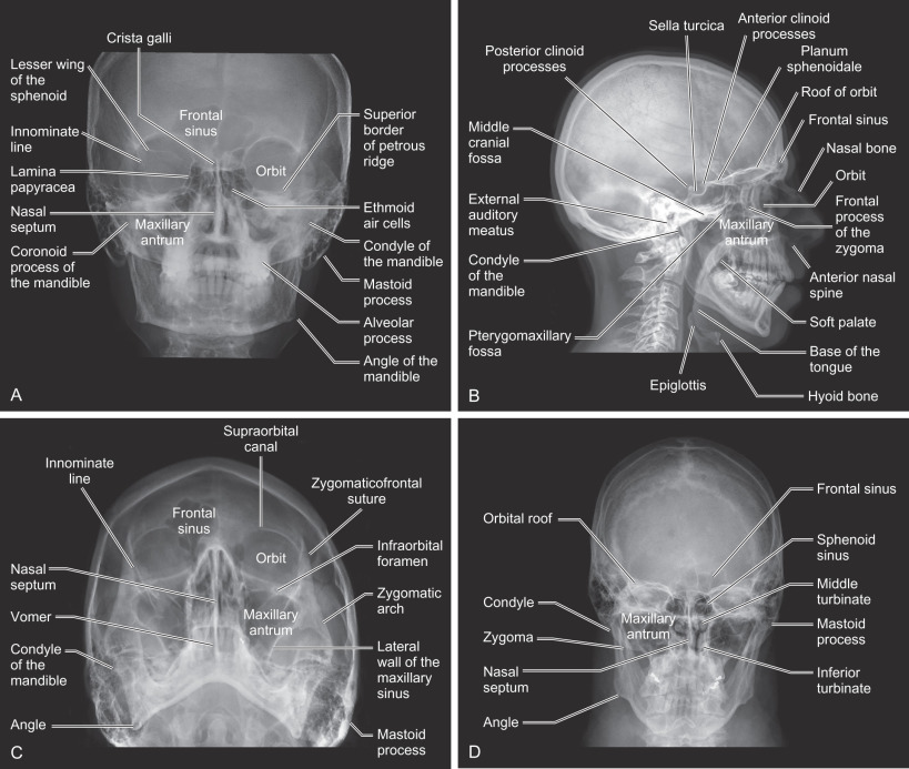
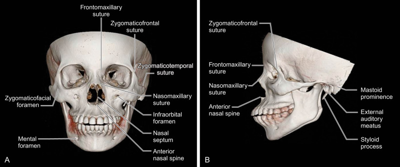
Radiographs of the skull at various angles allow visualization of the major osseous structures of the face and mandible. Plain radiographs are named based on the projection of the X-ray beam. The most common radiographs of the face in the trauma setting include: standard occipitomental (30 degrees OM or Waters view), posteroanterior (PA skull or Towne view), reverse Towne’s and the true lateral skull ( Fig. 1.2.1 ). The submentovertex view, which requires hyperextension of the neck, is not obtained given the risk of a concomitant cervical spine injury seen in 2.2% of patients with maxillofacial fractures. Each projection of the face best demonstrates certain osseous features of the craniofacial skeleton ( Table 1.2.1 ). However, overlapping osseous structures limit evaluation of the entire craniofacial skeleton, especially the midface, sinuses, and skull base. Moreover, the patient must be able to cooperate with positioning to obtain the various projections. This is impossible with patients suffering from traumatic brain injuries associated with craniofacial fractures.
| Waters (30 degrees OM) | Towne’s (AP Skull) | Reverse Towne’s | True Lateral Skull | |
|---|---|---|---|---|
| Cranium | ✗ | ✗ | ||
| Midface fractures | ||||
| Le Fort I | ✗ | |||
| Le Fort II | ✗ | |||
| Le Fort III | ✗ | |||
| Paranasal sinuses | ||||
| Frontal sinus | ✗ | ✗ | ||
| Sphenoid sinus | ✗ | |||
| Maxillary sinus | ✗ | |||
| Mandible | ✗ | |||
| Mandibular condyle | ✗ | |||
| Coronoid process | ✗ |
Panoramic Radiography
The panoramic radiograph (orthopantomogram or panorex) displays the entire maxillomandibular region on a single image ( Fig. 1.2.2A ). The term panoramic radiography is derived from panorama, “an unobstructed view of a region in every direction.” There are two different ways of obtaining panoramic views, which are defined by the location of the radiation source: intraoral or extraoral.
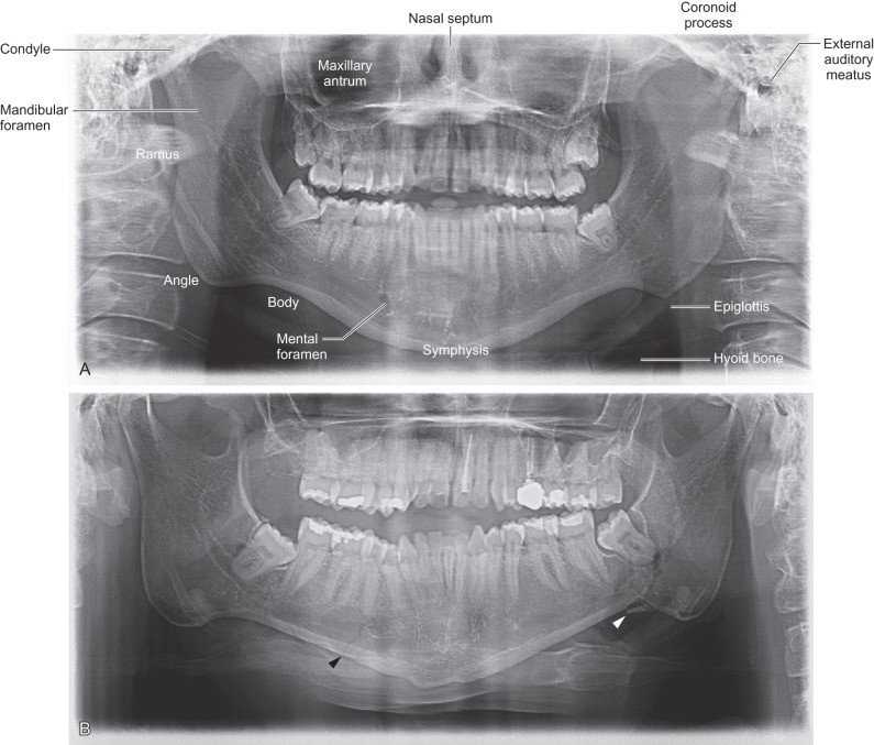
The intraoral technique requires a small X-ray tube be placed in the patient’s mouth where radiation is directed through the jaws to expose a film placed just outside of the targeted facial anatomy. The first patient undergoing this procedure was reported by a German inventor, Horst Berger. The extraoral technique, which is the most popular method in use today, employs an extraoral source of radiation that rotates around the patient. To create a panoramic view, objects in front or behind the focal trough are blurred, leaving a sharp image of the entire mandible in one 2-dimensional plane facilitating the diagnosis of mandible fractures and dentoalveolar trauma ( Fig. 1.2.2B ).
Panoramic radiographs are fast and convenient with minimal training needed for the operating technician. Moreover, panoramic radiography provides the lowest radiation dose with broad coverage of maxillomandibular bones and teeth. This imaging modality is most advantageous for stable patients who cannot tolerate intraoral procedures or examination. The limitations of the radiographs include unequal magnification across the image, making linear measurements unreliable, as well as difficulty imaging both sides of the mandible when the patient has severe maxillomandibular discrepancies causing malocclusion. The tomographic technique of the exam also creates artifacts, including double images of the hyoid bone, cervical spine, and epiglottis. Ghost artifacts, which are higher than the true anatomic location on the opposite side of the image, are created by the upward inclination of the X-ray beam. These artifacts, in addition to the superimposition of overlying structures, limit the complete evaluation of the maxillomandibular structures, especially the mandibular condyle and coronoid process which overlap the mastoid prominence and midface, respectively.
Computed Tomography (CT)
In computed tomography, an X-ray tube rotates around the patient emitting a fan-shaped beam of X-rays that are detected by a row of detectors on the opposite side. Initially, the X-ray tube and detector rotated synchronously around the patient for one cycle then the table would move a small increment (i.e., 5 mm) for the next scan or slice image. This was known as the “step and shoot” method or so-called incremental scanners. In 1989, CT scanners acquired image data in a helical fashion where the X-ray tube and detectors continuously revolve around the patient while the table advances the patient through the gantry. This overlapping image data results in higher spatial resolution, improved multiplanar reconstructions, faster scanning and reduction in radiation dose. Multidetector CT scanners were introduced in 1998 beginning with a 4-detector row CT scanner and progressing to the current state-of-the art CT scanners with up to 320-detector rows allowing for multiple slices to be captured quickly and simultaneously, reducing exposure time and motion artifact. This also results in improved resolution and quality of the axial, reformatted, and 3-dimensional images of the face. Current technology allows data obtained via CT to be transmitted to the operating room for computer-assisted surgery, including presurgical planning and intraoperative navigation during the repair of craniomaxillofacial injuries.
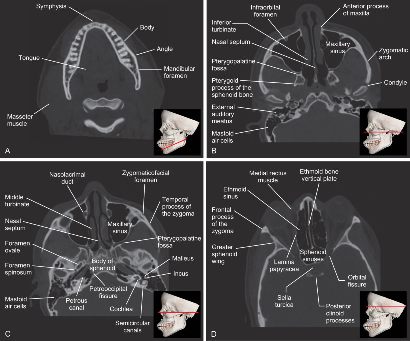
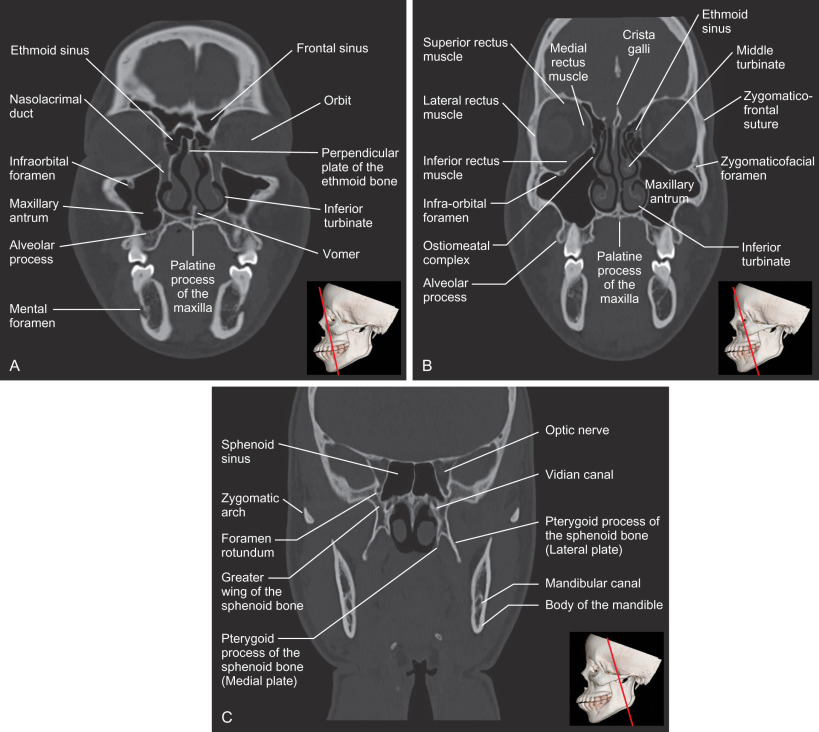
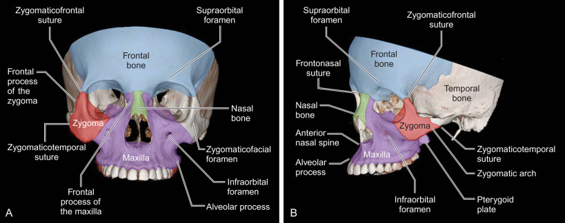
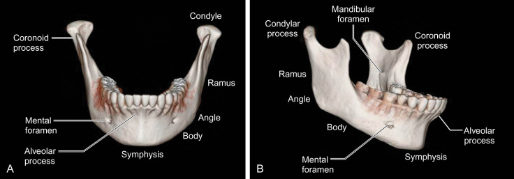
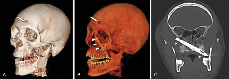
In comparison to plain radiographs of the face, CT eliminates the superimposition of structures and provides high-resolution contrast of the osseous structures and soft tissues that can be viewed simultaneously in three orthogonal planes as well as 3D ( Figs. 1.2.3–1.2.7 ). This allows for complete evaluation of the face, skull base, cranium, and brain. In a large study, it was reported that the most common fractures were to the midface (71.5%) with supraorbital and frontobasal skull fractures present in 4.2% of the cases. CT is superior to plain radiographs when assessing the mandible, especially nondisplaced symphyseal fractures, given the overlapping spine on the AP Towne’s view. CT has a higher accuracy, sensitivity, and specificity (90%, 90%, 87%, respectively) for condylar fractures when compared to panoramic radiographs (73%, 70%, 77%, respectively). CT has also been shown to detect additional fractures not seen on plain or panoramic radiographs, often leading to a change in operative management. In the setting of penetrating trauma, multidetector CT is the best imaging modality to assess the trajectory of the missile and injury to the adjacent soft tissues and vascular structures ( Fig. 1.2.8 ).
Magnetic Resonance Imaging (MRI)
The first MR image was described by Paul Lauterbur in 1973. By the early 1980s, MRI was available for clinical use. The patient is placed into a magnetic field that causes the spin of the hydrogen atoms within the soft tissues to align with the magnetic field. The scanner then directs a radiofrequency (RF) pulse into the patient that redirects the spin of the hydrogen atoms. When the RF pulse is turned off, as the spin of the hydrogen atoms returns to that of the external magnetic field, a signal is released and detected by a coil in the scanner which is used to create the MR image.
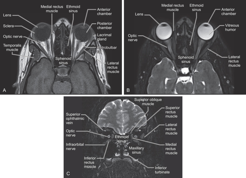
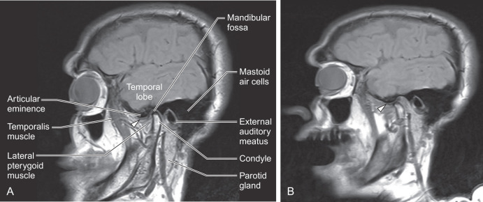
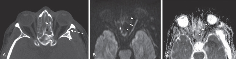
Advantages of MRI include noninvasive imaging without ionizing radiation, and soft tissue resolution in multiple planes that is superior to computed tomography ( Figs. 1.2.9 and 1.2.10 ). In the setting of craniomaxillofacial trauma, MRI can be used to evaluate the optic nerve for traumatic optic neuropathy (TON) ( Fig. 1.2.11 ), as well as herniation of orbital contents into the adjacent maxillary sinus or traumatic encephaloceles. A study by Freund et al. demonstrated that MRI showed the inferior rectus muscle to be herniated through the orbital floor fractures twice as often as when compared to the evaluation of the orbital contents using CT. Although MRI is suboptimal in assessing cortical bone given the paucity of hydrogen atoms, it can depict bone marrow edema associated with chronic complications of trauma such as mandibular osteomyelitis, ischemic necrosis of the condylar head, and traumatic damage to the articular disc. The disadvantages of MRI include high cost, long scan times, metallic hardware that can obscure adjacent structures, and other relative contraindications to MRI.
Related posts:


Stay updated, free articles. Join our Telegram channel

Full access? Get Clinical Tree


