Percutaneous Heart Valves, Aortic and Other Stents, and Other Interventional Hardware


Key Points


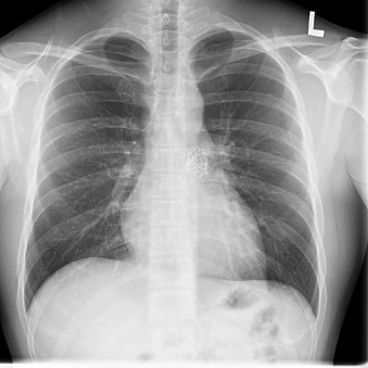
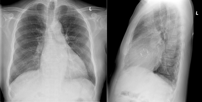
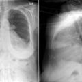
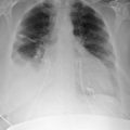
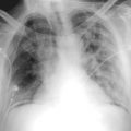
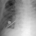
  • Percutaneously inserted heart valves are evident on chest radiography.


  • The position of percutaneous heart valves can be visualized by chest radiography, as can some complications and dysfunction.


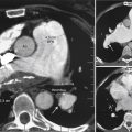
  • (Thoracic) aortic stenting can be visualized by chest radiography, as can stenting of a wide range of other vessels and structures.


  • A wide range of other percutaneously delivered devices and material can also be visualized on chest radiography.


Percutaneous Heart Valves


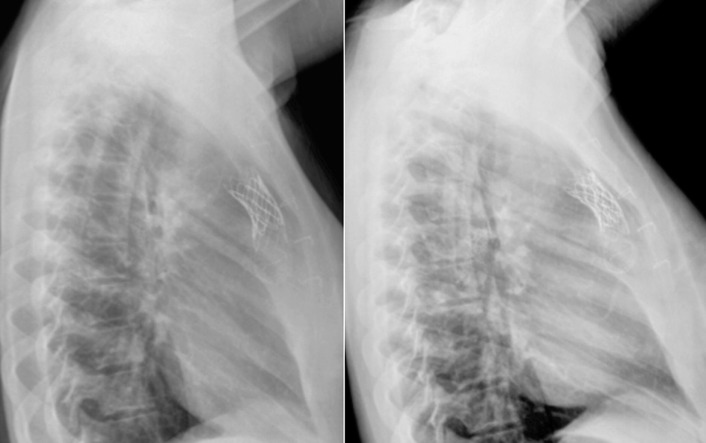
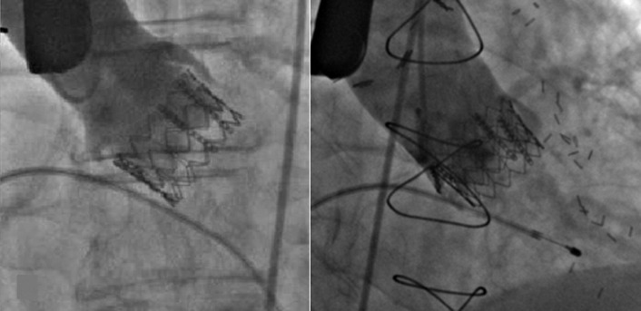
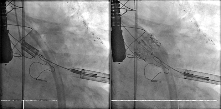
Transcatheter/percutaneously inserted heart valves are increasingly implanted. Most commonly, they are inserted into the pulmonic position or right heart conduits in the previously repaired congenital heart disease population ( Figs. 13-1 and 13-2 ) and into the aortic position ( Table 13-1 ; Graphics 13-1 and 13-2 ; Figs. 13-3 to 13-10 ), but they can also be placed into atrioventricular valve positions and into bioprostheses or conduits in any position.


Figure 13-1


Lateral chest radiographs of a Bonhoeffer stented valve in the pulmonary position on the left image early after implantation and on the right image several years later. Over time, the strut mesh has fractured.


Figure 13-2


Chest radiograph of a patient with a percutaneously inserted Melody valve placed in the pulmonic position.


TABLE 13-1

Percutaneous Valves


VALVES COMPOSITION RADIOPACITY METHOD OF INSERTION
Aortic Valves
Edwards Lifesciences Equine pericardial tissue Radiopaque stainless steel stents (shorter) NA
CoreValve Bovine pericardial tissue Radiopaque nitinol stent (longer) NA
ENABLE Aortic Prosthesis, Model 6000 Equine pericardial tissue Radiopaque nitinol stents, radiopaque posts Via femoral artery retrograde approach
ENTRATA Aortic Prosthesis, Model 7000 Equine pericardial tissue Radiopaque stainless steel frame Via transapical anterograde approach
Edwards Ascendra Equine pericardial tissue Radiopaque stainless steel stents (shorter) Via transapical anterograde approach
Pulmonic Valves
Medtronic Melody transcatheter Equine pericardial tissue Radiopaque platinum stents (shorter) Via femoral venous insertion
Medtronic Melody transcatheter right-sided valve conduit Equine pericardial tissue Radiopaque stainless steel stents (shorter) Via femoral venous insertion
CoreValve Bovine pericardial tissue Radiopaque nitinol stent (longer) NA

NA, Not applicable.


Graphic 13-1


Schematic representation of the radiographic appearance ( left images ) and drawings of the CoreValve ( right images ), seen side-on ( upper images ), and from top down ( lower images ).


Graphic 13-2


“En-face” ( upper images ) and side-on ( lower images ) illustrations of the radiographic ( left images ) and actual ( right images ) appearance of the Edwards Sapien percutaneous aortic valve.


Figure 13-3


Transapical Sapien percutaneous valve in the aortic position and transapical Sapien percutaneous valve in the mitral position within a bioprosthetic mitral valve.


Figure 13-4


Fluoroscopy during percutaneous transapical insertion ( left image ) and deployment of Edwards Sapien valve ( right image ). Note the fluoroscopic appearance of transesophageal echocardiography probe.


Figure 13-5


Sapien percutaneous valve in the tricuspid position within a bioprosthetic tricuspid valve. Note the bioprosthetic mitral valve.


Figure 13-6


Fluoroscopic images and photograph of the Edwards Sapien percutaneous aortic valve seen side-on ( upper images ), seen end-on radiographically ( lower left image ), and seen top-down in actuality ( lower right image ).


Figure 13-7


Fluoroscopic views approximately side-on of a percutaneously inserted Edwards Sapien aortic valve prosthesis. Note as well the pacemaker and the internal thoracic artery bypass graft clips, as well as the prior sternotomy wires.


Figure 13-8


Posteroanterior and lateral chest radiographs of a patient without a prior thoracotomy who has undergone percutaneous insertion of an Edwards Sapien aortic valve prosthesis.


Figure 13-9


Transapical Sapien percutaneous insertion of a Sapien valve in the aortic position ( left image ) and after deployment ( right image ). Note the previous sternotomy wires.


Figure 13-10


Transapical percutaneous insertion of a Sapien valve in the aortic position. Note the bioprosthesis in the mitral position, sternotomy wires, and surgical clips along a left internal thoracic artery graft.


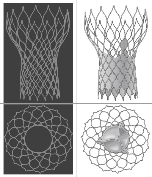
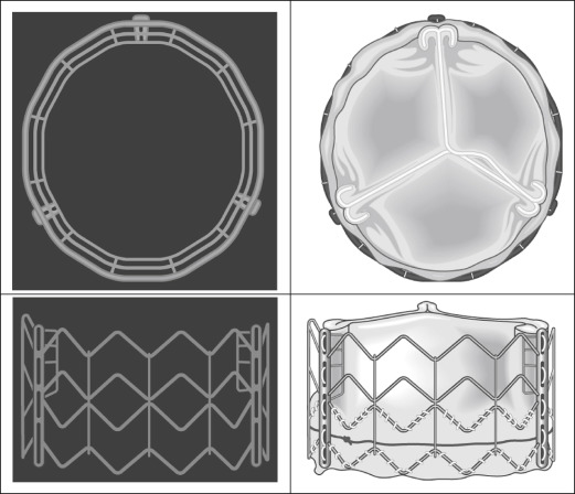
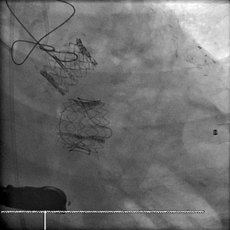
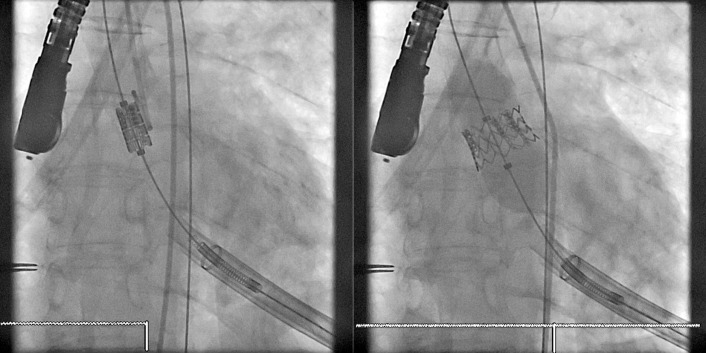
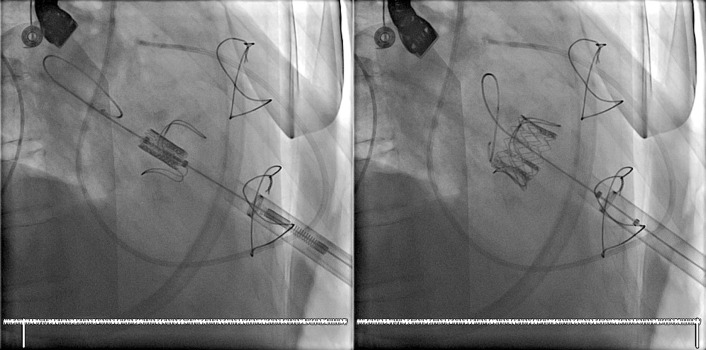
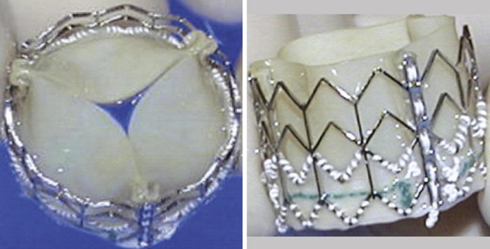
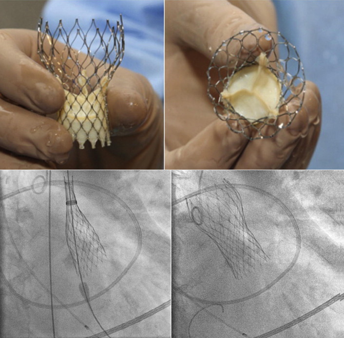
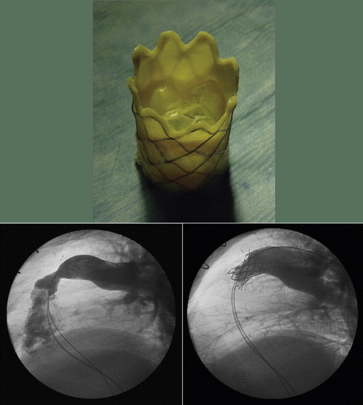
Percutaneous valves are generally supported by radiographically obvious stents, the design of which allows for initial contraction of the prosthesis onto a catheter and release/self-expansion from the catheter.


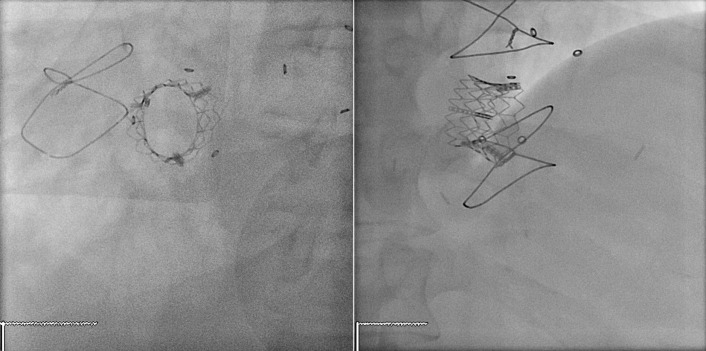
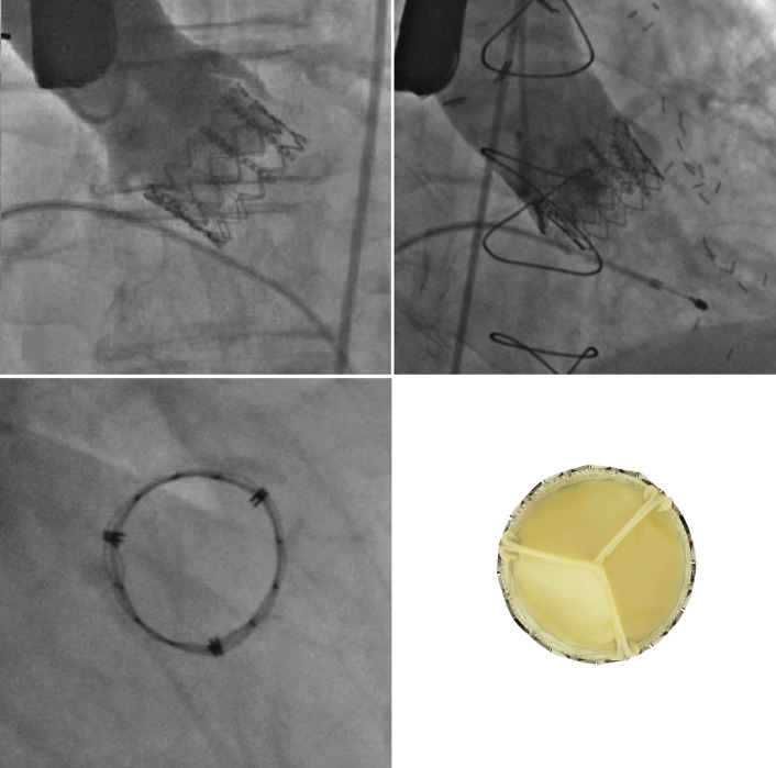
Percutaneous/transcatheter heart valves are constructed of either bovine jugular venous valves that are suspended on wire mesh cages (Bonhoeffer design/Melody Transcatheter Pulmonary Valve–TPV, Medtronic), or consist of a valve created from bovine pericardial tissue that is suspended on wire mesh cages (Edwards Sapien and Medtronic CoreValve). Percutaneous aortic valve implantation is currently one of the most rapidly proliferating percutaneous interventions in the world ( Figs. 13-11 to 13-13 ).


Figure 13-11


Edwards Sapien Stent-Fixed Transcatheter Xenograft. Valve size and stent diameter is 23 mm. Left image : Outflow view; right image : lateral view. (From Walther T, Falk V, Dewey T, et al: Valve-in-a-valve concept for transcatheter minimally invasive repeat Xenograft implantation. J Am Coll Cardiol 50:56–60, 2007. Used with permission.)


Figure 13-12


Upper images : Third generation of the CoreValve prosthesis (18-F) before loading into the delivery catheter. Lower images : Implantation of the CoreValve Prosthesis. Prosthesis partially released (still possible to retrieve the valve) ( lower left image ); prosthesis completely released ( lower right image ). (From Grube E, Schuler G, Buellesfeld L, et al: Percutaneous aortic valve replacement for severe aortic stenosis in high-risk patients using the second-generation and current third-generation self-expanding CoreValve prothesis device: success and 30-day clinical outcome. J Am Coll Cardiol 50:69–76, 2007. Used with permission.)


Figure 13-13


Upper image : The percutaneous bovine jugular venous valve mounted within an expandable platinum-iridium stent (Numed, Hopkinton, USA). Lower images : Percutaneous pulmonary valve stent insertion. Severe pulmonary regurgitation ( lower left image ) is absent following the deployment of the valve ( lower right image ). (Upper image from Coats L, Tsang V, Khambadkone S, et al: The potential impact of percutaneous pulmonary valve stent implantation on right ventricular outflow tract re-intervention. Eur J Cardiothorac Surg 27:536–543, 2005. Used with permission.)


Figure 13-14


Chest radiographic views of six patients with a Gore thoracic aortic endograft.


Aortic and Other Stents


Aortic Stenting ( Figs. 13-14 to 13-23 )


Thoracic aortic stenting/endografting is increasingly performed as treatment of coarctation of the aorta, aneurysm of the thoracic aorta, false aneurysm of the thoracic aorta, penetrating ulcers, and dissections ( Table 13-2 ). Thoracic aortic stenting may employ either uncovered or (ePTFE)-covered stents, depending on the nature of the lesion and the desired intervention. The supportive wire network of aortic stents is readily visible on chest radiography. FLOAT NOT FOUND FLOAT NOT FOUND FLOAT NOT FOUND FLOAT NOT FOUND FLOAT NOT FOUND FLOAT NOT FOUND FLOAT NOT FOUND FLOAT NOT FOUND FLOAT NOT FOUND FLOAT NOT FOUND


Apr 10, 2019 | Posted by in General Surgery | Comments Off on Percutaneous Heart Valves, Aortic and Other Stents, and Other Interventional Hardware

Full access? Get Clinical Tree

Get Clinical Tree app for offline access