Abstract
To date, 3-dimensional imaging is fundamental to adequately diagnose craniomaxillofacial trauma, particularly orbital trauma. However, not only preoperative 3D imaging is required but also tools for intra- and postoperative quality control are needed. In craniomaxillofacial trauma and reconstruction it is imperative to assess the quality of reduction and reconstruction, particularly in cases where implants have been inserted. In this context, intraoperative 3D imaging using C- and O-arms became recently popular and is therefore considered both a valid alternative and a line extension to intraoperative real-time navigation for intraoperative quality assessment. If neither intraoperative 3D imaging nor real-time navigation is available, postoperative 3D imaging should be performed.
Keywords
intraoperative imaging, C-arm, cone beam computed tomography, CBCT, intraoperative navigation, quality control
Background
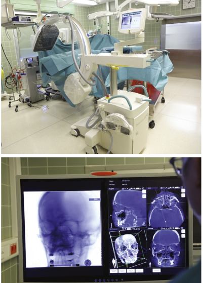
The idea behind intraoperative imaging is to avoid postoperative imaging and secondary revision procedures by allowing the intraoperative confirmation and adjustment of fracture reduction and hardware placement as necessary. This should save time, resources, reduce the number of operations, and improve results. Different imaging modalities are available intraoperatively, including magnetic resonance imaging (MRI), computed tomography (CT), ultrasound (US), and cone beam computed tomography (CBCT). Today, intraoperative imaging using CBCT mainly refers to so-called 3D C- and O-arms. The terms “C-arm” and “O-arm” originate from the shape of the device ( Fig. 1.3.1 ). Basically, intraoperative imaging can be performed using either portable or static devices. C- and O-arms are available as mobile and static devices. CT and MRI scanners are usually static devices and might be integrated into hybrid operation theaters.
The usage of intraoperative C-arms or image intensifiers began in the 1960s. Contrary to craniomaxillofacial surgery, intraoperative imaging has been performed for more than half a century in orthopedic surgery. Today, orthopedic surgery without intraoperative imaging is unimaginable. This is based on the fact that initially only 2-dimensional (2D) images could be obtained which were not suitable to display the complex 3-dimensional (3D) anatomy of the facial skeleton, particularly of the orbit. Plain radiographs of the skull, for example, panoramic, Waters view, submentovertex (jug-handle view), or lateral radiographs, are difficult to interpret because of the effects of superimposition. In midface fractures, orbital wall involvement cannot be ruled out using conventional 2D imaging. Furthermore, the resolution of those images, particularly concerning orbital walls, is inadequate for accurate diagnosis. Thus, 2D and 3D imaging should be used for diagnosis and treatment planning of craniomaxillofacial fractures, particularly of the orbit. Today, multislice computed tomography (MSCT) and cone beam computed tomography (CBCT) are the imaging modalities of choice for diagnosing midface fractures. Both techniques were found to be suitable for imaging midface fractures in all 3 dimensions and to help assess whether orbital reconstruction is required.
The transfer of the postoperative radiological examination into the operation theater has not only offered the chance of immediate revisional surgery but has also substituted conventional radiographs with a 3D data set. Thus, CT and CBCT should not only be used for diagnosis and treatment planning in craniomaxillofacial trauma but also for postoperative quality control. In most institutions postoperative CT or CBCT scans are used. Not until motorized cone beam systems with 3D CT-like image data sets were introduced, was intraoperative imaging attractive to craniomaxillofacial surgery.
Intraoperative Cone Beam Computed Tomography
Three-dimensional C-arm devices that are also referred to as angiographic image intensifiers were initially used in cardiac and vascular surgery. Meanwhile, they have increasingly been used since the end of the 1990s. These advances have also enabled the use of such 3D C-arms for intraoperatively displaying the facial skeleton. Thus, this technology has increasingly been used over the last decade in oral and maxillofacial surgery. As mentioned above, C-arms are portable or can be fixed or mounted to the ceiling, to the ground, or even to robotic arms.
The principle behind this technique is a cone-shaped X-ray bundle. The conical shape of the beam distinguishes this technique from helical or spiral CT, which used a fan-shaped beam. The X-ray source and the detector (image intensifier or flat panel detector) rotated around a field of interest of the patient. By rotating the beam around a fixed point (isocenter) in the object of interest and acquiring projections from many different angles, a typically cylindrical 3D volume can be reconstructed. Although a 360 degree rotation is used in general, some devices have implemented a 180 degree or slightly greater rotation arc, which suffices for image reconstruction and leads to significant radiation reduction. Conventional intraoperative 3D C-arm devices consist of an isocentric C-arm and the motorized devices allow rotations of 190 degrees around the patient. As a result of the acquisition of 2D projections throughout this rotation, only a single rotation 360 degrees or less is needed to acquire a full (3D) data set.
The images received by the detector are then compiled into volumetric data (primary reconstruction). This can then be visualized as 2D multiplanar reformatted slices or in three dimensions by using surface reconstruction or volume rendering. Typically, a few hundreds of projections are collected. The 2D attenuation profiles obtained from all angles are then reconstructed into a 3D matrix, containing volume elements (voxels), each having a certain grey value which represents the average density within this volume element. As examples, a few devices that are frequently used in craniomaxillofacial surgery are described in Table 1.3.1 .
| Company | Product Name | Intended Use | H × W × D of C-arm frame, cm (in.) | Image Intensifier, cm (in.) | Image Matrix Size | Generator | Navigation Aids | Differences From Competition |
|---|---|---|---|---|---|---|---|---|
| Ziehm Imaging | Vision RFD 3D | Fluoroscopy, interventional radiology | 30 (12) FD: 159 × 80 × 188 (62.6 × 31.5 × 74); 20 (8) FD:160.3 × 80 × 189.4 (63.1 × 31.5 × 74.6) | Flat-panel detector 30 (12)/ flat-panel detector 20 (8) | 1024 × 1024 | 25 kW | Roadmapping; interface to image-guided surgery 2D | 20 kW powerful monoblock generator; SmartVascular; up to three synchronized touchscreen user-interfaces; large flat-panel; advanced active cooling for nearly unlimited X-ray time; SmartArchive; SmartDose |
| Siemens Healthcare | Arcadis Orbic 3D | Surgical fluoroscopic imaging | 215 × 80 × 180 (84 × 31 × 71) | 23 (9) | 1024 × 1024 | 2.3 kW | Yes | 3D visualization and navigation |
| Philips Healthcare | Veradius Neo | Interventional procedure visualization | 169 × 81 × 73 (66 × 32 × 29) | Flat detector 26 (10) | 1280 × 1024 | 15 kW | Digital navigation link, landmarking, pixel shift, roadmapping, SmartMask, trace mode | Optimized C-Arm geometry; new distortion-free Trixell FD with 103 dB dynamic range; 15 kW generator; cardiovascular packages; 12-in. stand monitor for operator |
Today, intraoperative 3D C-arms should be connectable to devices that allow for intraoperative real-time navigation. In addition, DICOM-Data generated by the 3D C-arm can be fused with the preoperatively created virtual planning so that an immediate intraoperative superimposition of planning and result are possible in the operating room.
Indications for Intraoperative CBCT
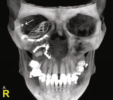
Basically, the indications are more or less the same as compared to conventional postoperative CBCT or CT. The major advantage of intraoperative imaging can be seen in procedures in which intraoperative verification of the surgical result is crucial and would lead to secondary corrections. According to recent literature, the major indication for intraoperative CBCT is craniomaxillofacial trauma, particularly fractures of the zygomaticomaxillary complex (ZMC), including posttraumatic orbital deformities. However, multiple different indications have been described in the literature. Intraoperative CBCT has also been used in orthognathic surgery, in maxillary and mandibular reconstructions with bone grafts. In gunshot injuries it was shown to be useful in the detection and removal of metallic foreign bodies. Intraoperative imaging using a 3D C-arm was used during mandibular fracture repair, particularly of the condylar process and the condylar head. In those cases the postreduction result of the fragments or the position of the condylar head in the glenoid fossa are crucial. Three-dimensional intraoperative imaging using a C-arm device was also described as a practical device in evaluation and verification following bone grafting procedures, including sinus floor augmentation. Furthermore, CBCT data generated by intraoperative mobile systems were shown to be sufficient for the planning of dental implant position. As mentioned above, intraoperative imaging can also be used in combination with intraoperative real-time navigation. Finally, preoperative CT or MRI in infants often requires general anesthesia. In children with preoperatively proven indications for surgical treatment, preoperative imaging under general anesthesia was substituted by intraoperative CBCT scans.
In summary, hard tissues can be displayed sufficiently using intraoperative 3D C-arm devices. The integration of flat panel detectors in advanced mobile CBCT systems will overcome the current disadvantages, such as limited data volume and insufficient soft tissue visualization. However, one disadvantage is the fact that the field of view cannot be altered in this system, resulting in imaging of areas that are not of primary interest.
Intraoperative CT and MRI
CT and MRI scanners are usually static devices and are mainly part of so-called hybrid operation theaters. Meanwhile, CT scans have emerged as standard imaging modalities in the diagnosis and treatment of craniomaxillofacial trauma and reconstruction, particularly of the orbit. Multislice systems with secondary coronal reconstructions have superseded primary coronal scans. However, the installation of an intraoperative fan beam CT scanner in a hybrid operation theater is associated with enormous costs and requires a complex infrastructure. However, the high resolution of intraoperative CT scans and the size of the scanning volume can be considered a major advantage, particularly in panfacial fractures. So far, CT is superior to all other imaging modalities in craniomaxillofacial trauma. Particularly, the fine anatomy of the orbit can be displayed most suitably using CT. Its disadvantages include high doses of radiation emitted, the high procurement costs and, as with magnetic resonance imaging, the imperative need for the presence of a radiologist with basic knowledge in craniomaxillofacial surgery, surgical demands, and sterility. This final disadvantage may result in intraoperative delays as well. Therefore, intraoperative CT is so far not recommended as a routine intraoperative imaging modality in craniomaxillofacial surgery.
In addition, intraoperative MRI is also not in routine use in craniomaxillofacial surgery. This is due to the fact that bony structures and inserted radiopaque implants are not displayed sufficiently. Further disadvantages include the extended scanning time, the complex intraoperative handling, and the need for a radiologist to be present.
Intraoperative Real-Time Navigation
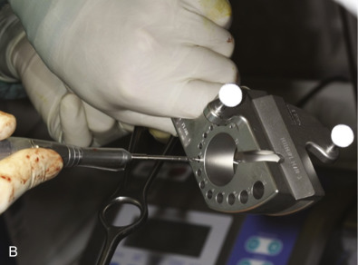
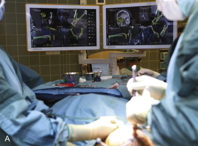
The use of intraoperative real-time navigation has been increasingly described in the field of craniomaxillofacial surgery. Today, this technique is routinely used in many institutions. The major advantage of intraoperative infrared-based navigation includes its radiation-free application in the operating room. In addition, multiple instruments including drills and burrs can be registered and tracked that allow their intraoperative real-time navigation. According to virtually determined trajectories, position, orientation, and path of movement of the instrument can be controlled in real time using an autopilot function ( Figs. 1.3.2 and 1.3.3 ). However, a preoperative CT or CBCT data set is always required for the determination of registration markers. The fact that this technique is based on a preoperative scan means that topographic changes during surgery result in discrepancies between the preoperative image data and the surgical site.
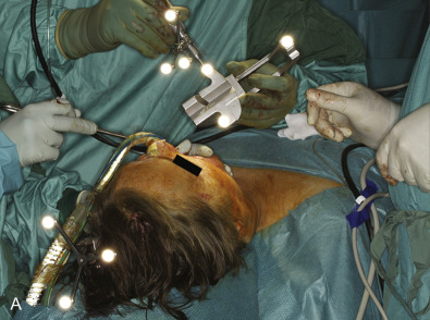
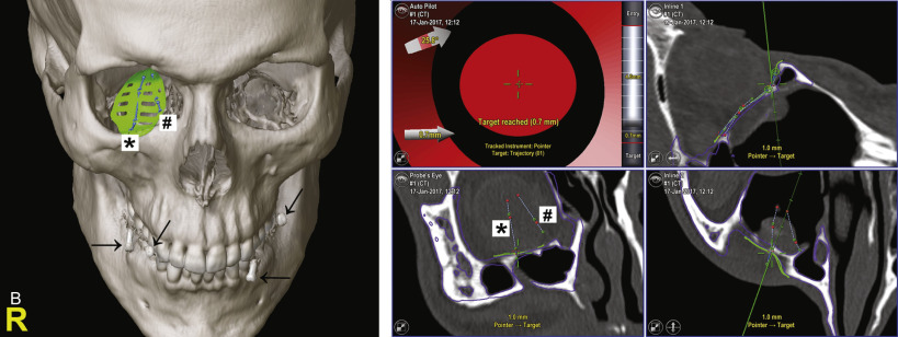
There are various markers that can be used for registration, including anatomical landmarks, dental-based navigation splints with radiopaque markers (screws), or previously inserted navigation screws. Anatomical landmarks for registration can be defined using the initial CT or CBCT scan. However, an additional CT or CBCT scan is required in case navigation splints or navigation screws are used ( Fig. 1.3.3B ). Meanwhile, frameless registration can be realized in the craniomaxillofacial region using a laser surface scanning system in order to avoid radiation exposure. Computer-assisted preoperative planning is required to virtually reduce fractures or reconstruct defects by mirroring. Intraoperatively, the patient’s position and anatomy need to be registered to the preoperative CT or CBCT data set using a “skull reference base” that needs to be fixed to the patient’s skull. Thereby, the patient’s position during the procedure can be tracked. Intraoperatively, the quality of fracture reduction as well as the planned position and shape of an implant can be checked in real-time sensing. It could be shown that intraoperative infrared-based navigation significantly improves the precision of orbital reconstruction using different titanium implants. The use of navigation also had a significant effect on the precision of the orbital volume reconstruction.
Recently, intraoperative imaging has opened up new perspectives in the field of intraoperative navigation. The renewal of intraoperative 3D imaging in maxillofacial surgery was mainly driven by the disadvantage of intraoperative navigation systems being based on preoperatively acquired imaging data that increasingly differ from the surgical site with ongoing surgery. Today, 3D C-arm devices generate DICOM data sets that are usable for intraoperative navigation. However, contrary to real-time navigation that is planned and registered on preoperative CT or CBCT data sets, fluoroscopic images (2D/3D) are used for the combination of intraoperative imaging and intraoperative navigation as originally described and used in spinal surgery. Meanwhile, the intraoperative acquisition of 3D fluoroscopic data sets for real-time navigation in craniomaxillofacial surgery has already been introduced. Finally, it could also be shown that 3D fluoroscopic data sets revealed an accuracy for navigation comparable to CT. Unfortunately, fusion of 3D fluoroscopy data with other 3D modalities could not be clinically realized up to today. But regarding high-contrast structures, an intraoperative updating by 3D fluoroscopy seems possible in the near future.
Surgical Anatomy in 3D Imaging
As previously mentioned, 2D images are not suitable to display the complex 3D anatomy of the facial skeleton, particularly in complex posttraumatic and congenital deformities, contour-relevant reconstructions, skull base surgery, and orbital deformities. Thus, high-resolution 3D imaging is recommended in the diagnosis as well as in the postoperative or intraoperative quality control of those cases. Distinct anatomical regions in the facial skeleton require distinct pre- and postoperative images, or if available, intraoperative imaging in order to be able to reconstruct complex anatomical regions. Those regions particularly include midface (zygomaticomaxillary region) and orbit, skull base, and the frontobasal region, as well as the condylar processes. Today, the indication for surgery should depend on the results of the diagnostic 3D imaging rather than 2D radiographs. Thus, the detailed anatomical information provided by 3D imaging allows craniomaxillofacial surgery to meet the requirements of a true-to-original reconstruction.
Goals of Reconstruction
The goals of reconstruction in the craniomaxillofacial region are:
To get things …
- •
Right, that were right (e.g. primary trauma)
- •
Better, that had been made wrong (e.g. secondary trauma)
- •
Adequate, that were never right (e.g. congenital)
- •
More adequate after tissue loss (e.g. postablative)
In order to achieve a true-to-original reconstruction, the anatomical features discussed below have to be taken into consideration.
Radiological key elements exist that should be analyzed in the preoperative 3D trauma scan first and, in case of reconstruction, again in the post- or intraoperative 3D imaging. The advances of high-resolution 3D imaging and computer-assisted surgery have given new insights into the details of orbital anatomy and have transformed the basic understanding of internal surface contours in relation to volume, ocular globe position, and binocular function. In general, the contralateral unaffected side should always be analyzed and provide a template.
Radiological Key Elements in Orbital Reconstruction
- •
Shape of the orbital walls, e.g. “lazy-S shape” of the orbital floor
- •
Volume of the orbit
- •
Posteromedial bulge
- •
The posterior ledge
- •
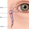
The nasolacrimal canal
- •
The inferomedial orbital buttress (transition zone between medial orbital wall and floor)