Fig. 2.1
A patients orthoroentgenogram showing multiapical deformities in the lower extremities
Congenital deformities around the knee joint
Acquired posttraumatic deformities (malunions)
Acquired hypertrophic nonunions with deformities
Sequelae of poliomyelitis
Contraindications include the following:
Presence or a history of infection
Deformities in the pediatric age (before physeal closure)
Long bones that are sclerotic and/or are narrow (medullary canal <7 mm)
2.3 Examination
Physical examination should include documentation of the range of motion of the adjacent joints, muscle strength, and neurologic status. Clinical length alignment and discrepancies should be noted and then measured radiographically.
2.4 Imaging Studies
An orthoroentgenogram in both planes should be obtained according to the following guidelines (Fig. 2.2):
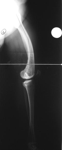
Fig. 2.2
A sagittal standing orthoroentgenogram showing long bowing deformity at the femur
The knee should be at maximum extension, especially in the lateral view.
The x-ray beam should be level with the knee joint and taken from a distance of 10 ft away (3 m) so as to minimize magnification.
One-centimeter blocks should be used to level the pelvis in the AP view.
A magnification marker is used to determine the size and diameter of the IM nail and to determine the number and level of the osteotomy(ies) (Fig. 2.3).
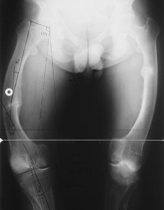
Fig. 2.3
Deformity analysis is performed on the x-ray of the right femur. A metallic marker is placed to predict the size of the IM nail
2.5 Preoperative Planning
Deformity analysis should be performed according to the deformity planning guidelines given by Paley et al. (CORA planning method using joint orientation lines) (Paley and Tetsworth 1992; Paley et al. 1994) (Fig. 2.3).
Determination of the level(s) of the osteotomy(ies) should be conducted.
If the deformity is at the distal femoral metaphysis, retrograde IM nail insertion should be performed through the intercondylar notch.
The diameter and size of the IM nail should be determined based on the scaled AP and lateral x-rays of the affected bone segment(s).
Digital or paper tracing should be performed to simulate the surgery and to determine the provisional and final position of the bone segment, according to the following factors (Figs. 2.4 and 2.5):
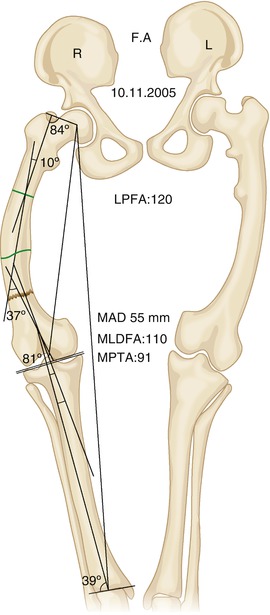
Fig. 2.4
Paper-tracing according to deformity analysis prior to correction

Fig. 2.5
Paper-tracing depicting the planned deformity correction. Note the placement of interference screws
The location of the extra, custom-made hole(s) on the IM nail should be determined.
The location and the number of interference screws (polar) should be determined in a manner that increases the stability of the construct (Fig. 2.5).
2.6 Surgical Technique
2.6.1 Equipment
Radiolucent table
Radiolucent knee support or a rolled, sterile towel
Large-field fluoroscopy
Flexible intramedullary reaming system
6-mm conical Schanz screws
Unilateral external fixator (EBI Monorail System or Orthofix LRS)
1.8-mm Kirschner wires (bayonette type)
3.5-mm cannulated drill bits
Intramedullary nail
2.6.2 Positioning
The patient is placed in the supine position on the radiolucent table, and the affected hip should be slightly elevated using a silicone bag under the buttock to provide a lateral view of the femoral deformities (Fig. 2.6).

Fig. 2.6
Radiolucent bag underneath the buttock to enable lateral view with the C-arm, and ease the antegrade insertion of femoral nails
Fluoroscopy from the hip to the ankle joint should be accessible (Fig. 2.7).
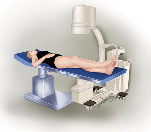
Fig. 2.7
Preoperative checking with the C-arm from hip to the ankle
If a long grid is available, it is placed under the matress of the patient.
Sterile preparation should be used prior to draping the entire lower extremity beginning at the anterosuperior iliac spine
2.6.3 FAN for Femoral Deformity
For distal femoral deformity corrections, retrograde intramedullary nailing is preferred. For more proximal deformities, antegrade intramedullary nailing is more suitable.
In the presence of severe distal femoral valgus deformities (greater than 15°), the authors recommend prophylactic peroneal nerve release.
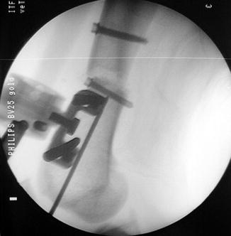
Two pairs of 6-mm half pins that are perpendicular to the anatomic axis of the femur (5–7° to the diaphysis, and 8–10° to the knee joint line) are inserted proximally and distally, respectively (Figs. 2.8 and 2.9). In the sagittal plane, it is crucial that the pins avoid any contact with the intramedullary nail (Figs. 2.10 and 2.11). Since the nail enters posteriorly, the distal half pins should be based anteriorly. Proximally, the nail is located anteriorly. The half pins should be located posteriorly at the level of the lesser trochanter.
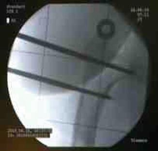
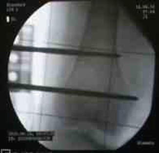
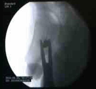

Fig. 2.8
AP view of the Schanz screws perpendicular to the anatomic axis of proximal femur

Fig. 2.9
AP view of the Schanz screws perpendicular to the anatomic axis of distal femur

Fig. 2.10
Posterior placement of the Schanz screws at the proximal femur to allow insertion of the IM nail

