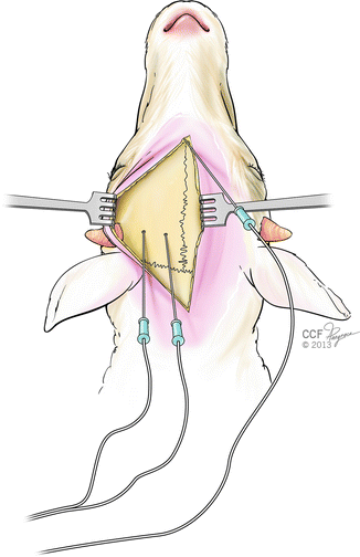
Fig. 52.1
Maximal nerve conduction velocity measurements. Stimulating hook electrodes are placed proximally and recording electrodes are placed distally to the repaired nerve segment
Placing Recording Electrodes
SEPs are recorded from the sensory cortex following stimulation of the peripheral nerve. After direct electrical stimulus to the median nerve, SEPs can be registered from the surface of the contralateral scalp, with the greatest signal obtained over the postcentral brain region. Based on our experience, however, the greater amplitude and more accurate measurements can be obtained transcranially with small point electrodes placed directly over the brain sensory cortex Kwiecien et al. [16].
With the sheep in lateral position, a scalp area is shaved and prepared with povidone iodine solution and then draped in the usual manner. A 6–8 cm skin incision over the midline of the scalp is made, widely exposing the skull bilaterally. Sagittal and coronal sutures should be easily visible. Next, an array of several burr holes is created in the parietotemporal location using a small 3 mm surgical drill. First two holes are drilled on the line connecting center points of each horn, 2 and 4 cm from the midline. Then, another sets of two holes are burred 1 and 2 cm anteriorly and posteriorly to the line (Fig. 52.2). Since the SEPs from both median nerves will be recorded, it may be preferable to drill the holes on the other side of the skull at the same time. Special attention needs to be paid not to penetrate the dura, which may result in injury to the brain and inability to record reliable data. Appearance of the clear, yellowish fluid at the burr side indicates injury to the dura and cerebrospinal fluid leakage.


Fig. 52.2
Transcranial placement of the recording electrodes for somatosensory evoked potentials measurements
The recording teflon-insulated monopolar needle electrodes are placed over the subdural space of sensory cortex.
Placing a Ground Electrode
The right position of the ground electrode is crucial for recording SEPs because of the electrical artifacts produced by the stimulation. To minimize these artifacts, the ground electrode should be placed on the stimulated limb proximally to the stimulating electrodes. A flexible metal band covered with saline soaked gauze wrapped around the limb serves well as a ground electrode. In case of isolated direct nerve stimulation, the ground electrode may be also placed subdermally on the head, which adequately eliminates artifacts related to the electrical interference (Fig. 52.2).
SEPs Measurements
After connecting the stimulating electrodes with the stimulus box and plugging the cortical and ground electrodes into the recording unit, the system is ready for SEPs measurements.
Most commercially available SEPs systems allow to choose between stimulation with either constant voltage or constant current. For the direct median nerve stimulation we prefer to use a constant current in the range from 1 to 4 mA. For each measurement, 100 stimuli are delivered at a rate of 1–10 Hz. These rates are considered optimal in most textbooks. However, it is worth to mention that lower rates are recommended for SEPs peaking more than 25 ms after stimulation, which is the case in sheep median nerve evaluation. In our laboratory, we use a rate of 4.5 Hz. It is important not to choose frequency of stimulation a multiple of 60 Hz. This can result in AC current interference from electrical devices in the operating room. Duration of stimulus should be in range 0.2–0.5 ms.
Each examination consists of three sequential measurements. After completing the data collection, average latency and amplitude values are calculated.
Maximal Nerve Conduction Velocity Measurements
Bipolar hook stimulating and recording electrodes are placed 1 cm proximally and 1 cm distally to the repair sites and the exact distance between electrodes is measured to calculate the conduction velocity (Fig. 52.1). After placing and connecting the electrodes, the system is ready for measurements. The position of the stimulating electrodes can be confirmed by turning on the stimulation and observing hoof twitching as a result of flexor carpi radialis activity. Stimulus intensity is adjusted to obtain the lowest threshold for the muscle contraction.
Stay updated, free articles. Join our Telegram channel

Full access? Get Clinical Tree


