Fig. 1
One skin replica illuminated from top (a) and right hand side (b)
At a micro scale the skin surface is not simply flat but able to be characterized by a particular micro-relief representing the keratinisation progress of epidermis and 3D organization of dermis and subcutaneous tissue [8]. The periodical cellular updating and frequent mechanical interaction with external environment also give skin the macro level net-like topographic structures in regular geometrical forms like triangles, polygons and line patterns. The roughness and palpation parameters of these geometrical structures can be used to estimate an overall size and depth of a cutaneous tumour [9]. On the other hand, skin colour/reflectance, another important element to give skin general appearance, originates from the chromophores including melanin, one main and particular chromophore directly indicating the invasive depth of the melanoma. It usually gives the melanoma bluish colour as the pigments penetrating in the deep dermal layer absorb a large amount of light with long wavelengths [10].
Therefore both the geometric and colour/reflectance information of skin lesion are potentially important for differentiating the MM from BLs. A working device called skin analyzer (SA) has been purposely developed with the capability to recover the orientation and reflectance of skin surface simultaneously by using multiple images captured from same viewpoint but illuminated from different directions [11]. This provides an effective way to simulate the procedure adopted by dermatologists in making a clinical diagnosis, i.e. look those suspicious lesions from different angles, pick up suspicious physical features, and then possibly feed the features into a specialized intelligent classification system (doctor’s brain) to conclude which class the lesion may belong to. Such an imaging system is expected to help objectively detect and quantify features which are not easily picked up by naked human eyes.
Characterizing Skin Reflectance and Geometry
When a beam of light projects onto the surface of skin, it will undergo hundreds of absorption and scattering before emission. This process makes the radiation distribution isotropic in all directions. The micro facet structure of the stratum corneum further contributes diffusive impression of the skin appearance [12]. Therefore a diffuse reflection model is used here to approximate the mechanism of the photons interacting with the chromophores and layered structure of skin. Based on this reasonably simplified skin optical reflection model the working SA device is able to recover both orientation and reflectance of skin surface simultaneously from the theory of photometric stereo.
Colour Photometric Stereo
The image intensity  of a Lambertian surface can be simply expressed as the product of the composite reflectance
  and the cosine of the incidence angle
  , i.e. the angle between the direction of the incident light
  and the surface normal
  :
:

Without any prior geometry knowledge of an object’s surface, more than one image is required to recover the surface normal and reflectance. In general several images are taken using the same imaging system from the same observation point, but for each the object is illuminated by a single light source from a different direction  (j = 1, 2,…, N, N
  3). A six evenly distributed light source photometric stereo method has been proposed to ensure that all visible points on a convex surface can be illuminated by at least three light sources, the minimum required for traditional photometric stereo [13]. Shadows and highlight can be eliminated by directly using the intensity values through a hierarchical light-source selection stratagem. The redundant information from the images illuminated through the use of the extra light sources can improve the accuracy of the recovery as well as overcoming the effects of highlights and shadows. With the wide accessibility of colour photographs which provide three values at three channels, an improved solution can be achieved by averaging the results on three channels after implementing the traditional photometric stereo approach separately [14].
 of a Lambertian surface can be simply expressed as the product of the composite reflectance
  and the cosine of the incidence angle
  , i.e. the angle between the direction of the incident light
  and the surface normal
  :
:
(1)
 (j = 1, 2,…, N, N
  3). A six evenly distributed light source photometric stereo method has been proposed to ensure that all visible points on a convex surface can be illuminated by at least three light sources, the minimum required for traditional photometric stereo [13]. Shadows and highlight can be eliminated by directly using the intensity values through a hierarchical light-source selection stratagem. The redundant information from the images illuminated through the use of the extra light sources can improve the accuracy of the recovery as well as overcoming the effects of highlights and shadows. With the wide accessibility of colour photographs which provide three values at three channels, an improved solution can be achieved by averaging the results on three channels after implementing the traditional photometric stereo approach separately [14].
Suppose  (c
(c  r, g, b) represents the intensity values of each pixel in three colour channels respectively within the
  th image,
  intensity values can form three groups of intensity vectors
  . In the same way, an illumination matrix can be obtained through arranging the lighting directions as:
  . So total
  equations from Eq. (1), corresponding to the same pixel in six images, can be written as the following linear system of equations:

When the matrix  is know through calibration, and is of at least rank 3, three groups of albedo and surface normal can be uniquely calculated using a linear least-squares method:


After discarding those problematic pixels, the above procedure is carried out for each of the three channels of the captured colour images respectively. Theoretically the surface normal calculated at three channels should be same. However some slight variation always exists in practice as there is usually noise within the acquired images and uncertainty in the estimation of lighting location. To minimize these errors, the mean of the three surface normal values is calculated as a standard optimal value. After the surface normal is determined, the composite albedo can be recalculated from Eq. (3) and then converted into RGB colour space to form the colour reflectance image.
 (c
(c  r, g, b) represents the intensity values of each pixel in three colour channels respectively within the
  th image,
  intensity values can form three groups of intensity vectors
  . In the same way, an illumination matrix can be obtained through arranging the lighting directions as:
  . So total
  equations from Eq. (1), corresponding to the same pixel in six images, can be written as the following linear system of equations:
(2)
 is know through calibration, and is of at least rank 3, three groups of albedo and surface normal can be uniquely calculated using a linear least-squares method:
(3)

(4)
Different from the available techniques which only measure either skin reflectance or skin topography [15, 16], this simplified reflection model allows both the reflectance and shape information recovered simultaneously and then provided as an improved input representation for differentiating suspicious lesions.
Evaluation of the Skin Analyzer
The SA is an ergonomically and aesthetically pleasing hand-held device designed and manufactured for undertaking pilot clinical studies. Figure 2 shows the schematic and prototype of the device which is finished in a black colour with a compact digital CCD camera and six surface mounted LEDs whose relative positions are optimized to achieve better recovery accuracy [13]. It can be easily operated through customized software interfacing with a PC or laptop. Due to the light-weight design, it can be held in a single hand without touching the skin being measured. This ensures the measurements have good repeatability and stability because any external distortion on the skin due to the contact is largely excluded from the skin surface during this non-contact imaging procedure.
Eight images are totally collected within one second for each clinical case. The first image, taken without any lights on is considered as the image under illumination from ambient light only. Following the first image acquisition, six images are acquired with each spot light in a different position sequentially activated. The eighth image is acquired with three equally distributed lights switched on at the same time to simulate a diffuse lighting condition. The effect of ambient light is eliminated by subtracting the first image from each of the later seven images. The device is evaluated through its performance in 3D reconstruction and rendering synthetic images for diagnosis purposes. The experiments are carried out on both skin replica and in vivo skin.
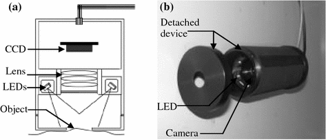

Fig. 2
Schematic (a) and developed handheld skin analyzer (b)
3D Reconstruction
A ground truth of skin surface is required in order to evaluate the performance of 3D recovery of the SA; however it is normally difficult to obtain a good ground truth of skin surface because of its elastic, dynamic and multilayered microstructure. A negative skin replica collected by smearing a silicon rubber material mixed with a catalyst is used. This provides a simple and repeatable means to record the external detailed structures of the skin without affecting the skin function. Fine detail in the form of the furrows and peaks of the skin relief can be reproduced exactly proving this process is carefully undertaken. After the skin replica has been produced, the topography of skin can be obtained by scanning the surface of the replica through either a contacting mechanical stylus or noncontact optical systems. These measurement techniques have proved useful for recording skin topography through static silicone replicas with satisfactory accuracy in analyzing skin microstructure and anisotropy. Here a commercial optical scanning device, phase shifting rapid in-vivo measurement of skin device (PRIMOS) is used to obtain the profile of skin replica as a standard reference for comparing with the data acquired by the skin analyzer [15]. The PRIMOS recovers a height map of skin surface from the images illuminated by a series of phase shifting stripe lights onto the skin or skin replica.
To make the surface normal extracted from the photometric stereo technique comparable to that output from the PRIMOS device, the 3D data from the PRIMOS is transformed into a gradient representation format through partial differentiation, which will not introduce any global error due to the local calculating operation. On the other hand, the gradient data obtained from photometric stereo approach is also integrated into a format of skin profile which can be compared with the PRIMOS height map directly, though the integration and comparison are only applied on a relative small area to minimize the effect from the accumulated errors with an integration procedure.
Figure 3 shows skin replica taken from normal skin on the back of a hand and the 3D topography representation in the form of needle maps and 3D reconstruction results. The rectangle area in Fig. 3a formed by the black solid lines specifies the interested area where the integration of surface normal and comparison are carried out.
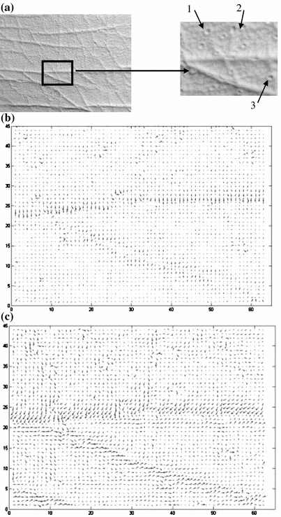
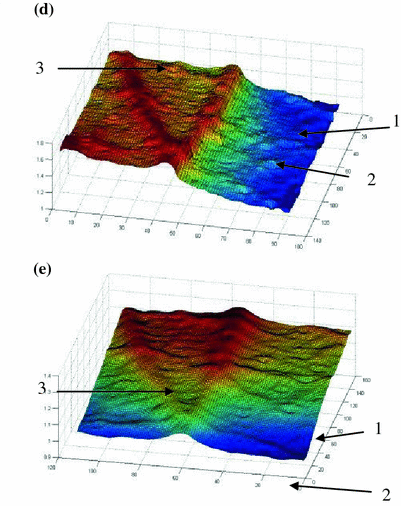


Fig. 3
Evaluation of geometry recovery on skin replica (a) through comparing the surface normal (b) and (c), 3D reconstruction (d) and (e) obtained from PRIMOS and SA
Figure 3b and c are needle maps extracted from the 3D data acquired by the PRIMOS and derived from the surface normal data captured by the SA. The SA demonstrates a higher sensitivity as more vectors are presented with long amplitudes. Meanwhile the reconstructed skin profile from the skin analyzer changes more smoothly, while sharp edges can be found with the results from the PRIMOS. This can be observed from the reconstructed results of three identified small holes in Fig. 3d and e. This failure of the PRIMOS in the recovery of sharp edges may be explained by the obstruction of light projected from only one direction. The skin analyzer is able to take advantage of the multiple light sources to remove the presence of shadow and specularities before recovery. This makes those edges and holes reconstructed from photometric stereo look more reliable and credible.
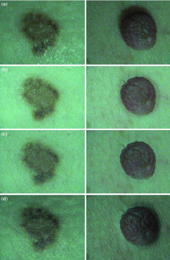

Fig. 4
Four type of images of two sample lesions (a) illuminated from one direction, (b) illuminated from all directions, (c) recovered with surface reflectance, and (d) rendered into virtual photographs
Skin replicas have been used as an acceptable means to investigate the topography of the skin. However it requires considerable operator skill to successfully copy the skin structure. Most importantly it cannot replicate skin colour information which is sometimes more important than skin microstructure in clinics. Meanwhile the serial of parallel black/white light stripes projected by the PRIMOS onto the skin surface may be concealed by the heavy pigmentation of skin lesions. It may deteriorate the accuracy and resolution of the reconstruction results [17]. The bulky weight also prevents the PRIMOS in vivo measurement of skin lesions distributing arbitrarily around the body. On the contrary the SA provides a new flexible mean to record the appearance of skin surface for either clinical or cosmetic purposes.
Synthetic Colour Images
Figure 4 shows four types of images used to assess the colour representation achieved by the SA. They are traditional photography captured with only one illumination (a), diffuse photograph illuminated by a ring-type of flash (b), reflectance reconstructed from multiple images with the elimination of specular and shadow effects (c), and images rendered by using a virtual light source (d). The eighth image illuminated by three equally distributed lights is used to simulate the idea diffuse or ring-type flash photograph, one of the popular manners to reliably record visual information of the skin lesions [18].
The photographs illuminated by one light in Fig. 4a present heavy highlight on the left of the lesion and shadows on the right side of the lesion. The diffuse (multiple) lights can resolve such problems to some extent in Fig. 4b, although illumination by diffuse light often does not produce an image with perceived depth and structure details as may be seen by the human naked eye. The fine scaling of valleys and bumps can hardly be discerned due to the effects of the diffuse illumination. It may make this method unacceptable due to the reduced fidelity and ‘unreal’ nature of the image especially when the topographic information is interested.
The PS approach can average the specular or shadow effects to obtain an approximation of the surface reflectance in Fig. 4c. Similar to diffuse photograph, the three-dimensional topographic details have been eliminated in reflectance image too. However the disappearance of skin structure texture in Fig. 4b is caused by the illumination from multiple directions, whereas the reflectance is the reflective properties of the skin and independent from the topography of the skin. When the reflectance is combined with the recovered surface orientation information, the skin surface can be fully characterized. Figure 4d shows a synthetic skin image, illuminated by a virtual light source. It is noticeable that both the colour and profile information are rendered effectively.
Reflectance Mapping for Segmentation of Lesions
The reflectance image reflecting the type, quantity and distribution of the chromophores under the skin is largely independent from the position and intensity of the illumination. Such objective information potentially offers significant benefit for outlining the lesion area and then differentiating between malignant and benign tumors. Here we examine its applications for the first step of automated diagnosis, i.e. the segmentation of skin lesion. Due to the lack of a reference method which could provide the exact boundary of lesion area, experienced dermatologists are invited to outline the border of the lesion on the conventional photographs and indicate using black lines. An established automated segmentation algorithm is used to separate the lesion from normal skin for both photographs in red line and reflectance images in green line [19].
As the automated segmentation algorithm works on the intensity of the images, the results of border tracking are sensitive to changes in the intensity values. Figure 5a shows that the boundary of the lesion tends to be larger than those in Fig. 5b and c. This is caused by shadows occurring during the photographing of the bumped and raised lesion, even though multiple light sources have been used.
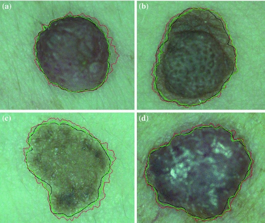

Fig. 5
Four pigmented skin lesions a intradermal naevus, b intradermal naevus, c basal cell carcinoma and d dermatofibroma, superimposed with manually segmentation result (black line), automatic segmentation result from the diffuse photograph (red line), and automatic segmentation result from the photometrically derived reflectance image (green line)
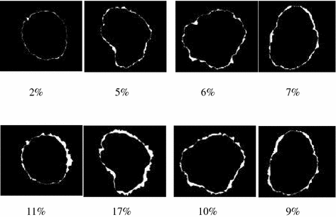
To compare quantitatively the automatic segmentation results obtained from conventional photographs with those obtained from reflectance images, a performance indicator was calculated by subtracting the area enclosed within the manually derived outline from that enclosed within the automatically derived outline, and then expressing this difference as a percentage of the area within the manually derived outline. Figure 6 provides the results in this form for all four lesions, as well as for a series of inverted binary difference images in which white areas indicate regions that lie within the automatically derived boundary but not within the corresponding manually derived boundary (the top row of results is from the reflectance images and the bottom row is from the conventional photographs).
