Key points
• Cephalometric analysis is performed in three-dimensions to allow the surgeon and the orthodontist to address asymmetry in all three planes.
• The time-consuming laboratory process of facebow transfer, plaster mounting of dental casts, sectioning, repositioning, and remounting of the dental casts are all eliminated.
• In addition to the physical examination, three additional components are needed for virtual planning (VP): CBCT data, 3D photos, and 3D dental casts (or intraoral scans).
• If the condyles are not properly seated within their glenoid fossa at the time of the CBCT scanning, then the accuracy of VP thereafter will be compromised. The technician performing CBCT should be educated on the critical impact of poorly obtained data.
• Direct optical scanning of the dental arches is more accurate than stone casts because it eliminates distortions from the impression material.
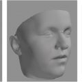
• To incorporate surface color and texture of the patient’s face into images in the composite skeletal and soft tissue models, 3D images can be acquired and superimposed over the scan.
• The 3D soft tissue data lack predictive algorithms to show the 3D response of soft tissue to skeletal movements, and this remains a topic of future research, with increasing accumulation of such data.
The problem
Surgeons and orthodontists are faced with the practical problem of objectively assessing a patient’s dentofacial skeletal deformity and then taxed with restoring the skeletal framework and the overlying soft tissue envelope to achieve an aesthetically pleasing face. Maxillofacial surgical planning is a multilevel process. It involves integrating the clinical assessment of the soft tissue envelope, the underlying facial skeletal structures, and the dentition. All three elements must be assessed independently and then as a composite to understand the deformity and the reconstruction required to optimize the desired final form.
The surgeon needs to determine which components of the skeletal structure need to be separated, repositioned, and then each of the elements placed in a new spatial position relative to the cranial base and relative to the alteration of the soft tissue envelope to optimize aesthetic appearance and functional outcome. Cephalometric analysis has been the “tool” for abstracting the complexity of the human craniofacial skeleton into a geometric scheme that would allow comparison with normative data and with the ideal surgical–orthodontic treatment goal. For more than half a century, this involved (1) obtaining two-dimension (2D) profile lateral radiographs by using a standardized cephalostat machine, (2) marking the key anatomic landmarks, (3) measuring linear distances and angles, and (4) comparing those measurements with a specific population norm. The orthodontist and the surgeon would then determine the ideal skeletal position and incisor relations. The treatment was then based on the mechanics needed to move the dentition using orthodontic appliances and surgery to move the skeletal bases to the desired geometric pattern.
However, this reduced the complexity of the three-dimensional (3D) craniofacial problem to a 2D planar problem in the sagittal plane, and the assumption was patients had an acceptable degree of facial symmetry. Although single profile assessment was sufficient for the vast majority of the patients who presented with developmental dentofacial deformities, treatment planning became less reliable in the case of patients with a significant component of facial asymmetry. This included patients with condylar hyperplasia, hemifacial microsomia, skull base asymmetries, and congenital cleft and craniofacial conditions. In such cases, surgeons and orthodontists would incorporate frontal cephalometric radiographs with the lateral cephalometric radiographs to add a third dimension in their planning. Nevertheless, the use of 2D radiographs in orthogonal planes remained less reliable, and frequently, surgical repositioning depended more on the surgeon’s assessment in the operating room. Consistent results were difficult to obtain. Surgical planning was piecemeal, time consuming, and not intuitive. It was definitely not surgical simulation or rehearsal of the in vivo experience.
Emerging three-dimensional technology
Since the 1980s, 3D computed tomography (CT) imaging with reconstruction of stacked 2D acquired data has become routinely available in the clinical setting. Compared with conventional 2D dentofacial cephalometric films, 3D images provided considerably better visualization and details of the morphology of the skeletal structure, the dental arches, and the overlying soft tissue. With the availability of 3D volumetric images, new tools were developed, allowing the surgeon to navigate away from the limitations of conventional 2D cephalometry. ,
In the last two decades, significant technical developments further enhanced the 3D medical imaging technology: multidetector spiral CT, with faster capture times and with higher resolution, cone beam CT (CBCT), with significantly less radiation and the ability to capture the data in the natural head position (NHP) of an upright patient, and 3D optical and laser surface image capture of the color and texture of the facial appearance within milliseconds. ,
Advances in both computer hardware and software within the last decade have enabled interactive display of data on personal computers, with the ability to selectively view soft tissue or skeletal hard tissues from any angle as cross-sectional images and 3D surface planes. Recent developments in 3D medical image analysis software have made it possible to build accurate 3D patient-specific, virtual anatomic models from high-resolution medical images, including CT and CBCT scans. Both in plane and in 3D, measurement tools allow clinicians to extract useful information conveniently. The anatomic landmarks can now be more accurately located without the averaging of a 3D projection onto a 2D cephalometric radiograph. Cephalometric analysis is no longer confined to the midsagittal plane and its orthogonal frontal facial plane. Analysis can now be performed in three-dimensions to allow the surgeon and the orthodontist to address asymmetry in all three planes.
Today, software for virtual surgical planning (VP) is capable of simulating surgical procedures with ever-increasing user applicability: from the imaging research laboratory to routine daily clinical application. The facial skeleton is treated as a solid 3D object in virtual space that can be digitally manipulated. Osteotomy planes can be defined, and the 3D facial skeletal object can be digitally sectioned into two separate solid objects, where each can now be moved independent of the other. The software treats the CT dataset as solid objects on which Boolean operations can be performed. 3D visual objects can be added and subtracted digitally. Registration and superimposition techniques make it possible to build a composite model based on both volumetric information from CT/CBCT scan and surface information of the dentition from laser or optical scans with greater clinical accuracy. Surgical planning can now be done in 3D space instead of in planar projection 2D cephalometric films. , The complex facial skeletal asymmetries can be addressed.
Moreover, inaccuracies and the time-consuming laboratory process of facebow transfer, plaster mounting of dental casts, sectioning, repositioning, and remounting of the dental casts are all eliminated. The surgeon now has the ability to easily execute various surgical options to optimize outcome. 3D anthropometric analysis is available to the surgeon and the orthodontist dynamically as the skeletal segments are manipulated. Regions of interference during the skeletal movement can be assessed and detected (e.g., in maxillary impaction and mandibular rotation cases), the dental roots can be visualized within a skeletal framework for interdental osteotomies, and the course of the inferior alveolar nerve can be visualized for mandibular osteotomies.
While 3D VP is increasingly becoming the new standard of care for surgical planning, the real breakthrough is transferring the virtual surgical plan to the operating room. For this, the VP technology has been integrated with established 3D printing (i.e., additive manufacturing) technologies. Common 3D printing techniques, such as stereolithography (SL), fused deposition modeling (FDM), selective laser sintering (LS), and even certain metals-based processes, such as electron beam melting (EBM), are being used to create physical templates, guides, and implants. VP integrated with 3D printing is capable of designing and fabricating patient- and procedure-specific physical instruments, osteotomy guides, various templates, and intermediate and final occlusal guidance or splints. The traditional geography-specific dental laboratory for orthognathic surgery is being transformed into a digital, web-based laboratory that is accessible at any location where Internet access gives the surgeon and the orthodontist, each at different physical locations, the tools to plan the procedure together. This collaboration happens in a synchronous way and requires that parties be online together to interact, review, design, and approve clinical goals. This synchronous collaboration is a powerful tool but is also labor intensive, requiring each party to set aside the same time to review and plan. Future asynchronous tools may enable similar interaction with the patient’s plan while allowing stakeholders to plan a time and a place of their convenience.
Virtual surgical planning
The discussion in this chapter, as such, will set aside the conventional 2D approach to surgical planning as only of historical interest and focus on the next generation of maxillofacial surgeons and orthodontists who will be fully immersed in three-dimensional virtual surgical simulation. Our current approach is outlined in Box 17.1 and is discussed in detail later.
Define the final dentofacial skeletal position
- 0.
Define the midsagittal plane as the facial midline. This is a critical initial step.
- 1.
Section the maxilla at the LeFort I level (classic); segmental, if needed.
- 2.
Section the mandible as a bilateral sagittal split osteotomy (BSSO) procedure.
- 3.
Coordinate the maxilla and the mandible in their final position based on the final and desired occlusion.
- 4.
In the frontal view:
- 4.1.
Center the maxillary dental midline coincident with the facial midline (translation).
- 4.2.
Correct the “roll” with the center of rotation at the maxillary dental midline.
- 4.1.
- 5.
In the submental vertex view, correct the “yaw” with center of rotation at the maxillary dental midline.
- 6.
In the sagittal view, correct the anteroposterior (AP) position to the desired facial plane, vertical (incisor display) and the “pitch” addressing incisor angulation and mandibular inferior border.
- 7.
Perform osseous genioplasty, as needed, to correct the facial plane and lower third vertical height and asymmetry.
- 8.
Reassess the “yaw” at the final position. This may require adjustment based on the impact on the temporomandibular joint (TMJ) and on the maxillary asymmetry at the osteotomy level.
Optimizing the maxillary and mandibular osteotomy pattern
- 1.
Mirror imaging is now carried out to compare the severity of the asymmetry after surgical repositioning.
- 2.
The classic osteotomy pattern can then be altered to a higher level LeFort osteotomy to include a component of the zygoma for malar prominence or an asymmetrical osteotomy to improve the final osteotomy (iterative optimization process).
- 3.
Mandibular border asymmetry and contouring can be assessed.
- 4.
Patients may require ‘custom” implants to improve asymmetry in with respect to shape that cannot be addressed by osteotomy repositioning.
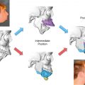
Define the intermediate position
- 1.
For maxillary first surgery, reset the mandible to the original or initial position.
- 2.
For mandibular first surgery, reset the maxilla to the original or initial position.
From virtual to three-dimensional (3D) printed physical operative guidance
- 1.
The osteotomy guides, the intermediate occlusal splint, the final occlusal splint, and the repositioning guide are then designed virtually and 3D printed as physical guides.
- 2.
3D-printed custom fixation plates can be designed and printed with 3D titanium printers.
The clinical examination
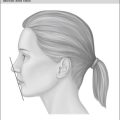
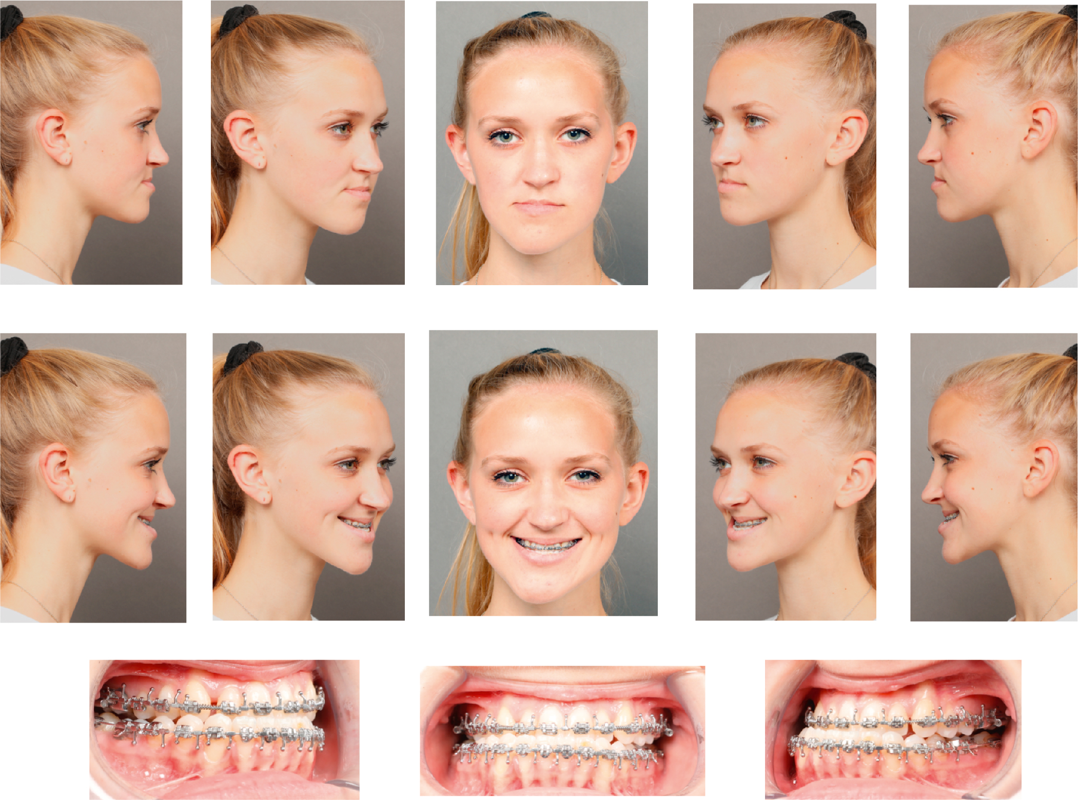
As with conventional orthognathic surgical planning, thorough physical examination and clinical anthropometric measurements are essential in the decision-making process involved in the planning. We must always remember that technology, no matter how advanced, can never be a substitute for a surgeon’s clinical examination and judgment. Ultimately, the outcome depends on the careful detailed clinical assessment that will guide all the subsequent planning to achieve the desired outcome. Clinical examination is the only way to obtain information with regard to the quality of tissues and their dynamic deformation with function (oral, airway, speech, smile, and facial expression). This is essential to guide the process of VP accurately, efficiently, and economically. During the physical examination, critical areas of concern should be head orientation (NHP), facial midline and relation to the dental midlines, occlusion (centric relation, centric occlusion, and habitual occlusion), dynamics of the smile, and temporomandibular joint motion. This dynamic information is critical because planning is based on static CBCT images and the surgeon does not have depth perception in the currently available VP software. All 3D digital imaging and thus planning are “trapped” within a 2D display. Although conventional 2D photographic images ( Fig. 17.1 ) are important, only the clinical examination can give the surgeon the true 3D assessment.
Three-dimensional data acquisition
In addition to the previously mentioned clinical information, three additional components are needed for VP: CBCT data, 3D photos, and 3D dental casts (or intraoral scans).
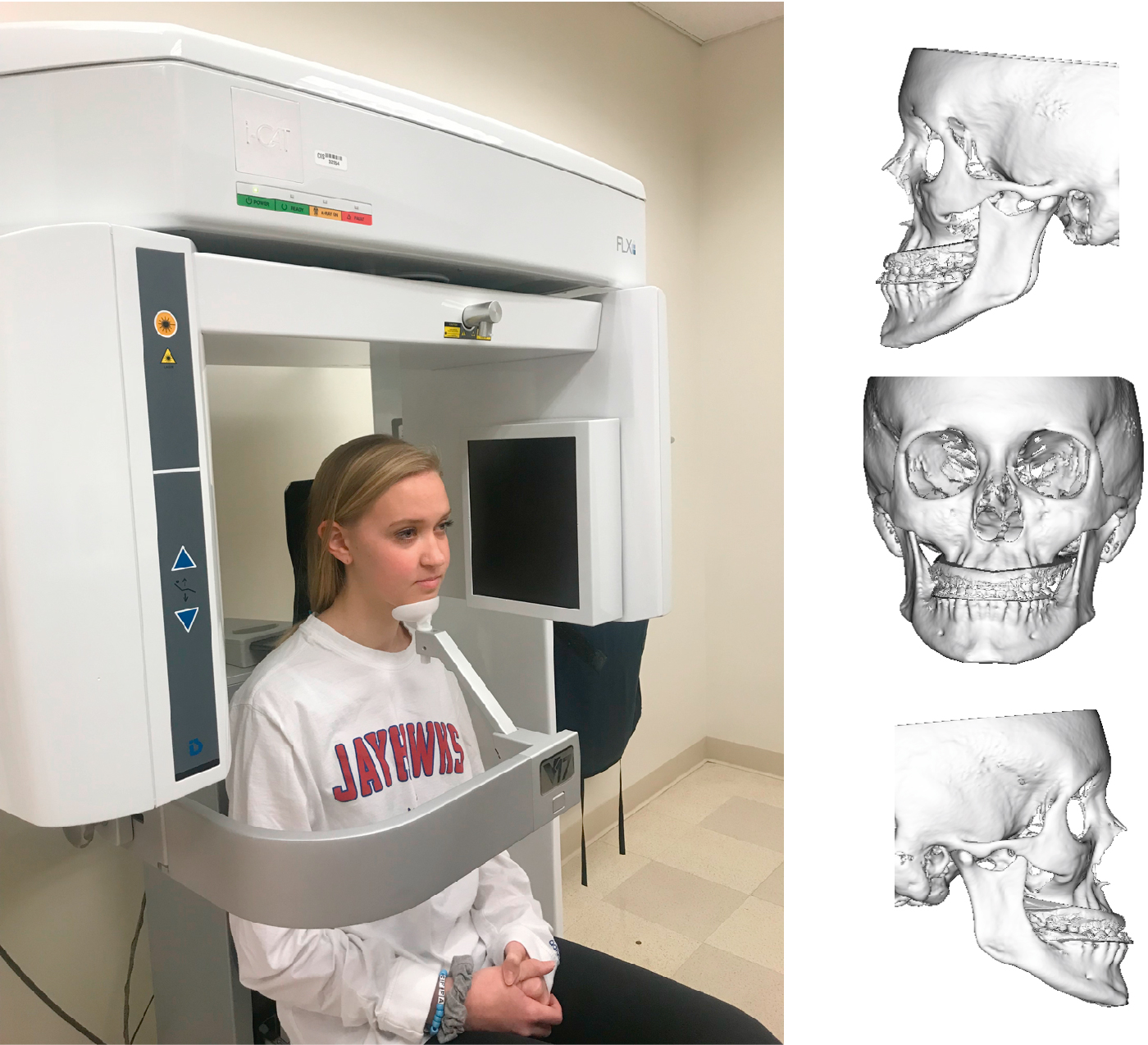
3D VP begins with acquiring CBCT scans in a consistent manner. The patient is positioned sitting upright with the head in the natural position, as depicted in Fig. 17.2 . The patient is asked to close the eyes at the time of scanning to reduce motion artifact. For the currently available CBCT scanners, the largest field of view needs be employed so as include the full face from the middle forehead inferior to the chin and hyoid and posterior through the temporomandibular joints. Currently, our scan protocol is 0.25 to 0.35 mm voxel size with a field of view of 22 cm. The patient should be in centric relationship, with the condyles positioned within the glenoid fossa. A thin-bite wafer may be utilized to help the patient maintain centric relation at the time of scanning. This is especially important for patients with class II relationship and a habit of unconsciously protruding their mandible. If the condyles are not properly seated within their glenoid fossa at the time of the CBCT scanning, then the accuracy of VP thereafter will be compromised. The technician performing CBCT should be educated on the critical impact of poorly obtained data.