Hip resurfacing is a surgical procedure whereby the femoral head is preserved and a component (mostly metal) is placed like a cap on the femoral head. The acetabular component is also a monolithic piece made of metal.
 Hip resurfacing offers the advantage that femoral bone can be preserved, and the femoral canal is not violated for fixation of the femoral component.
 The current hip resurfacing technique has a hybrid fixation. The femoral head is resurfaced through insertion of a cemented component. The cup is press-fit.18
Resurfacing Systems
 Resurfacing total hip arthroplasty (THA) with metal-on-metal bearing and hybrid fixation (a cementless acetabular component and a cemented femoral component) has been performed for many decades. In recent years, and with the issue of metal-on-metal bearing surface failure, the popularity of this procedure has waned.
 Several hip resurfacing devices of various designs are available, but the most critical factor affecting the outcome of resurfacing is the surgeon’s level of expertise.
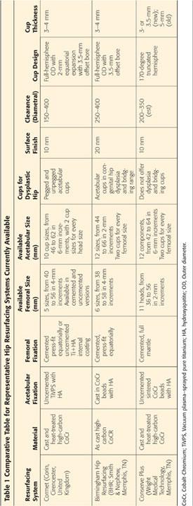
 Several manufacturers now produce metal-on-metal surface replacement components with a cementless acetabular component, a cemented femoral component, and a cobalt-chromium articulation. These various devices differ in terms of material, surface treatments, cup design, manufacturing process, carbide content, component thickness, clearance, possibility of including a cement mantle under the femoral component, fixation methods, and size ranges offered (Table 1).
SURGICAL MANAGEMENT
Indications
 Hip resurfacing is used optimally in younger, active patients with good bone quality.
 This procedure is indicated for a degenerative hip joint with pain and decreased range of motion.
 When joint-preserving procedures such as femoral osteotomy, acetabular osteotomy, or vascularized bone grafting are not ideal for an early stage of unambiguous coxarthrosis, hip resurfacing can be considered.
 Osteoarthritis of the hip joint is a good indication for resurfacing arthroplasty. Selective cases of osteonecrosis of the femoral head could be an indication for the need for resurfacing arthroplasty.
 Resurfacing is usually reserved for patients with good bone stock, high activity level, and a need for a high degree of motion.
 Hemiresurfacing, in which only the femoral head is resurfaced, has largely been abandoned because it provided suboptimal results.
 Resurfacing has been approved by the U.S. Food and Drug Administration.
 General indications for hip resurfacing are as follows:
Primary osteoarthritis
Secondary osteoarthritis as sequela of childhood disease, including hip dysplasia or infection
Osteonecrosis of the femoral head
Posttraumatic arthritis
Ankylosing spondylitis
Rheumatoid arthritis
Contraindications
 Abnormal anatomy of the femoral head or neck
 Severe limb length discrepancy that may require some correction during arthroplasty
 Severe bone deficiency
 Large and cystic lesions of the femoral head
 Large necrotic area of the femoral head
 Severe dysplasia because screw fixation for the acetabulum cannot be performed with resurfacing
 Fertile female patient
 The patient with renal disease
 Patients who have a metal hypersensitivity
Special Considerations
Osteonecrosis of the Femoral Head
 Osteonecrosis of the femoral head presents a special problem for hip resurfacing.
 The presence of a necrotic lesion of the femoral head can compromise fixation of the component.
 In general, survival of hip resurfacing is lower for avascular necrosis than for osteoarthritis in the counterpart hip. However, resurfacing arthroplasty for selective cases of osteonecrosis of the femoral head has comparative results with other etiology.2,19,31
Use of a Computer-Assisted Navigation System
 A computer-assisted navigation system is an intraoperative image-guided localization system used to enable proper cutting of bone and exact location of the implants in total knee arthroplasty or THA and in minimally invasive surgery.
 Although hip resurfacing arthroplasty has been used for a long time with acceptable results without any navigation system, one of the main concerns following resurfacing arthroplasty is femoral neck fracture.
In general, slight valgus positioning of the implant is recommended to reduce the tension and shear stresses across the head–neck junction, but intraoperative neck notching during femoral cutting often is a consequence of extreme valgus position.
Many mechanical femoral alignment guides have been developed to help surgeons achieve optimal positioning of the femoral implant.
 As for THA, early loosening or dislocation resulting from impingement due to the malposition of both components should be prevented.18
In hip resurfacing arthroplasty, avoidance of femoral notching by the femoral component and the position of the stem of the femoral component are critical. This may be technically difficult, even for an experienced surgeon, and it adds time to the procedure.
 Computer-assisted navigation systems have been developed to surmount the limitations of manual techniques.
Intraoperative navigation can demonstrate real-time positioning of instrumentation by imaging, thereby improving the accuracy of component positioning in hip resurfacing arthroplasty.
However, specific surface landmarks may be difficult to make out, and registration procedures are often the most time-consuming and accuracy-related segment of the procedure.
Irregular soft tissue distribution around the femoral neck also can affect navigation precision.
 Surgical navigation may be especially helpful during femoral procedures.
To reduce the potential risk of femoral neck fracture, we perform total hip resurfacing arthroplasty using computer-assisted navigation.
We have used the hip resurfacing systems from Vectorvision (BrainLAB, Munich, Germany) since 2005 (FIG 1).14
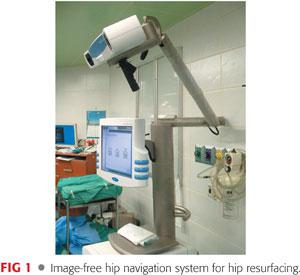
When using an image-free hip navigation system, the surgeon must digitize the pelvic and femoral planes of the patient to determine the individual pelvic and femoral coordinate system for prosthesis positioning.
Preoperative Planning
 Templates are used to determine approximate component sizes. Standard-sized conventional radiographs must be used rather than digital films, and the magnification factor must be taken into account.
 The femoral component must be sized so that there is no overreaming of the femur or risk of notching of the neck. Oversizing also should be avoided to preserve acetabular bone stock.
 Femoral component alignment is the most important preoperative consideration. Varus positioning must be avoided—neutral or slight valgus alignment is preferred (FIG 2). The authors recommend a femoral component axis shaft angle of 130 to 140 degrees.
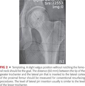
 When optimum femoral template positioning has been achieved, the distance from the tip of the greater trochanter to the pin insertion point on the lateral femoral cortex is measured with the ruler printed on the template.
 The relation between the exit point of the guidewire on the template relative to the lesser trochanter should be noted and reproduced during surgery.
 An acetabular component should be selected to fill the acetabular fossa and accommodate the selected femoral component.
Approach
 All of the standard exposures of the hip have been successfully used to perform surface replacement.
 Hip resurfacing is technically demanding, and the surgical approach should allow adequate exposure of the acetabulum and proximal femur without compromising postoperative muscle function.
 The posterior approach is the most popular approach for total hip resurfacing.
 The anterior approach, advocated by Wagner,28 is not popular.
 The anterolateral approach was described by Hardinge11 and modified by Learmonth.
Exposure of the femoral head is achieved by flexion, adduction, and external rotation of the lower extremity. Exposure of the acetabulum is accomplished by depressing the femoral head into a posterior and inferior position.
This approach has the advantage of preserving the posterior retinacular vessels, which reduces the possibility that an iatrogenic avascular state will develop postoperatively in the remaining femoral head.13
Critics of this approach believe that the exposure offered is inadequate, leading to a greater risk of complications and improper component positioning of both implants in total hip resurfacing. There may be a higher incidence of heterotopic new bone formation, and decreasing abductor muscle function often is compromised following this approach.21
 The transtrochanteric approach for hip resurfacing was popularized by Amstutz and Le Duff.2
This approach provides excellent exposure, but it is rarely used for this operation primarily because of problems associated with trochanteric osteotomy and a higher incidence of heterotopic ossification.
 The posterior or posterolateral approach is the standard approach used for total hip resurfacing.
In this approach, the tendon of the gluteus maximus is released to allow easy anterior displacement of the femur.
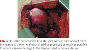
The capsule and synovium around the femoral neck are preserved as much as possible to prevent further vascular damage to the femoral neck and head. The femoral head is then dislocated (FIG 3).
The femoral neck is sized using neck gauges. Sizing also gives an idea about the minimum acetabular size required.
Usually, the acetabular preparation is done first, unless the femoral head is especially large, which results in inadequate acetabular preparation. In such cases, the femoral head is prepared at one or two sizes larger than the targeted femoral component size.
TECHNIQUES
 Posterolateral Approach
Exposure
The patient is placed in the lateral position.
The hip is flexed to 45 degrees and a straight incision is made, centered on the posterior edge of the greater trochanter.
Alternatively, the hip is extended and a conventional incision, curved posteriorly, is made (TECH FIG 1A).
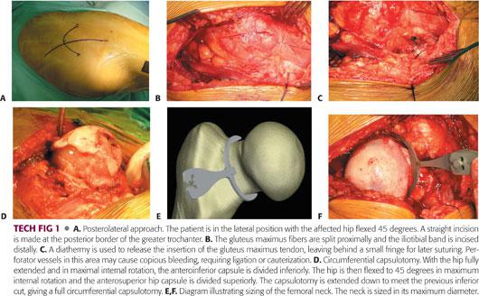
The fascia lata is incised, the fibers of the gluteus maximus are split, and a Charnley retractor is inserted (TECH FIG 1B).
The tendon of insertion of the gluteus maximus is usually released to allow subsequent easy anterior displacement of the femur; the underlying perforator vessels may require coagulation (TECH FIG 1C).
The trochanteric bursa is divided and swept posteriorly, after which the sciatic nerve may be easily seen or palpated.
The posterior edge of the gluteus medius is retracted anteriorly to reveal the piriformis tendon.
The fibers of the gluteus minimus are separated from the superior border of the piriformis tendon.
The interval between the gluteus minimus and the superior acetabulum and superior hip capsule is developed with electrocautery.
The hip is held in internal rotation and the piriformis tendon is divided as close as possible to its insertion, along with the hip capsule.
The other external rotators and the hip capsule are divided with electrocautery, leaving a cuff of quadratus femoris for later suturing.
The joint capsule is incised along the line formed by the superior margin of the piriformis muscle. The posterior capsule is detached cautiously, along with the base of the femur neck, to save intracapsular blood vessels around the femoral neck.
The femoral head is dislocated, the hip is fully extended (by bringing the knee to the midline), and maximum internal rotation of the leg is performed (TECH FIG 1D).
The anteroinferior hip capsule is divided, beginning inferiorly, just in front of the psoas tendon, using Muller capsular scissors or electrocautery.
The femoral neck is sized using neck gauges or templates (TECH FIG 1E,F); this also gives an idea about the minimum acetabular size required.
An anterolateral soft tissue pocket is created using a curved periosteal elevator or a Cobb elevator.
A Hohmann retractor is placed over the anterosuperior acetabulum and impacted into the anterior inferior iliac spine, and the leg is externally rotated to allow the femoral head to prolapse under the abductors into the pocket.
Acetabular Preparation
A pin retractor (Judd pin) is inserted into the ischium, retracting the posterior capsule and external rotators.
Two Hohmann retractors are placed from inferior to the teardrop, directed antero- and posteroinferiorly (TECH FIG 2A).
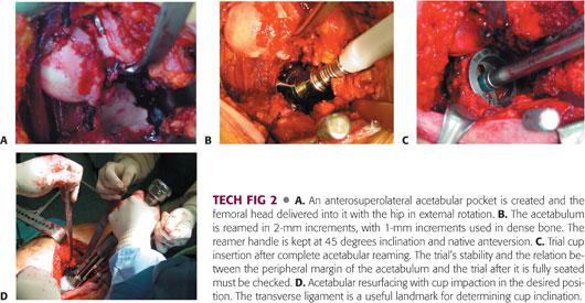
The labrum, transverse acetabular ligament, and other soft tissue in the cotyloid fossa are excised, giving a complete view of the bony acetabulum.
Sequential reaming is performed (TECH FIG 2B), with under-reaming by 1 to 2 mm.
An acetabular component that provides the best possible fit without reaming excess acetabular bone is preferred; this choice determines the size of the femoral component.
A trial cup is inserted and tested for stability (TECH FIG 2C).
The true acetabular component is then inserted in “native” version, usually 20 degrees and at a 45-degree angle (TECH FIG 2D).
Any protruding acetabular osteophytes should be removed.
The Hohmann retractors and pin retractor are removed.
Inserting the Guide Pin
The limb is then internally hyperrotated to expose the femoral head.
Lines are drawn on the center of the femoral head and neck in both anteroposterior (135 to 140 degrees of neck–shaft angle) and lateral planes (normal anteversion) and are extended up into the femoral head where they intersect (TECH FIG 3A,B).
The intersection point should be the entry point for the guide pin.
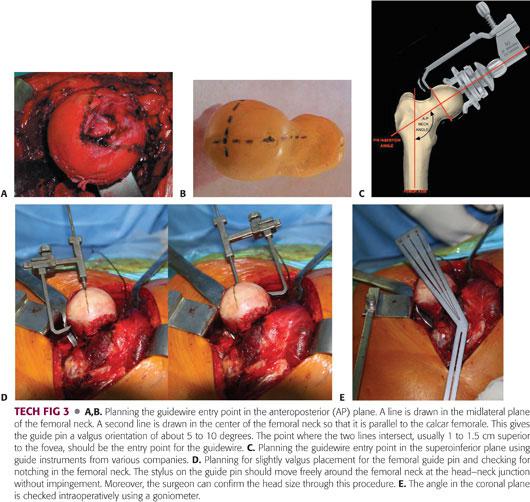
A guide pin is drilled into the femoral head and neck using a guide instrument (TECH FIG 3C).
A stylus is placed over the guide pin. This should pass around the femoral neck without impingement (TECH FIG 3D) to avoid notching of the femoral neck.
The guide pin is normally inserted from the superior part of the femoral head about 1 to 2 cm above the fovea.
In the coronal plane, 5 to 10 degrees of valgus is desirable; a 135- to 140-degree angle must be maintained with the long axis of the femoral neck (TECH FIG 3E).
Because a deformed femoral head or osteophytes around the femoral head and neck may make it difficult to recognize the actual state and relation of the femoral head and neck junction, excessive osteophytes should be removed carefully before femoral pinning.
Femoral Head Resurfacing
In most systems, femoral head preparation is done using cannulated reamers that pass over the previously inserted femoral guide pin (TECH FIG 4A).
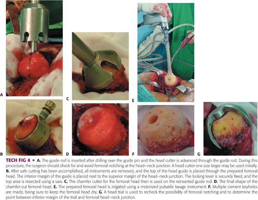
Consecutive reaming or milling using specialized instrumentation forms the femoral head into a chamfer-cut cylindrical shape (TECH FIG 4B–D).
Nonimpinging osteophytes present on the femoral neck are best left untouched.
Any necrotic bone in cases of osteonecrosis should be removed.
The femoral head is then pulse lavaged, and a suction vent is placed into the lesser trochanter to keep the femoral head dry and to prevent embolism (TECH FIG 4E).
A number of cement keyholes are drilled into the femoral head (TECH FIG 4F).
A final check is made to confirm that there has been no notching from the trial component (TECH FIG 4G).
Cementing
Bone cement is placed into the femoral component, which is then impacted onto the resurfaced femoral head (TECH FIG 5A,B).
Alternatively, in case of femoral head defect after curettage of necrotic bone, cement is applied to give a uniform 2-mm cement mantle around the femoral head (TECH FIG 5C), and the femoral component is placed over the head and lightly tapped into place (TECH FIG 5D).
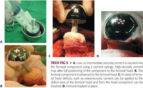
Check cement leakage; excess cement should be removed and pulse lavage used.
The joint is then reduced and tested for stability and range of motion.
Wound Closure
Good closure of the capsule and the external rotators is important.
The tendinous insertion of the gluteus maximus also is repaired, and the fascia lata, subcutaneous fat, and skin are closed.
 Special Technique for Osteonecrosis of the Femoral Head
Because the surgical approach and acetabular preparation are almost the same, only the technique for the femoral side is described.
Femoral Preparation
Accurate placement of the guide pin can be accomplished using pin alignment guides or a navigation system (TECH FIG 6A,B).
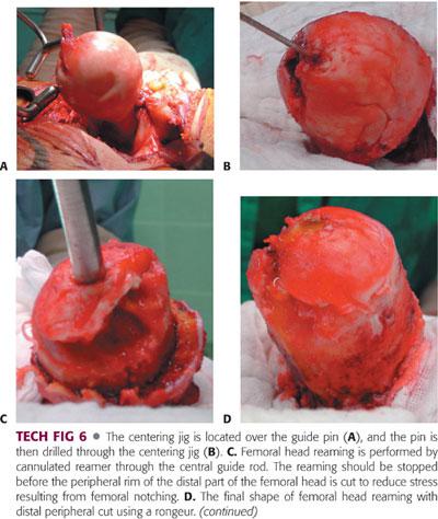
In most systems, femoral head reaming is performed by cannulated reamers that pass over the central guide pin.
A series of reaming or milling devices form the femoral neck into a cylindrical shape (TECH FIG 6C).
To reduce the stress resulting from femoral notching, reaming should be stopped before the peripheral rim of the distal part of femoral head is cut.
The remaining distal rim of the femoral head is carefully removed using a rongeur (TECH FIG 6D).
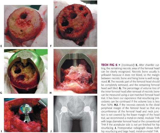
After chamfer cutting, the remaining necrotic area of the femoral head can be seen clearly (TECH FIG 6E).
Using a small curette and rongeur, the remaining necrotic area is removed and irrigated with aseptic saline to remove tiny fragments of bone debris (TECH FIG 6F).
The trial femoral head is inserted and the percentage of volume loss after removal of necrotic bone in the trial is measured (TECH FIG 6G).
In our experience, if the volume loss is less than 50% and the necrosis does not extend to the lower margin of the trial in any circumference of the femoral head and neck junction, resurfacing can be accomplished.
Otherwise, we recommend either metal-on-metal THA with a large diameter femoral head in cases where acetabular preparation has already been completed or conventional THA if preparation has not yet begun on the acetabular side (TECH FIG 6H–J).
Cementing
Using pulsatile lavage, thorough saline irrigation is repeated, taking care to keep the femoral head dry. The carbon dioxide (CO2) blow dry is useful for this purpose. A special suction system is used during the preparation of bone cement (TECH FIG 7A).
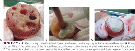
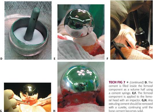
The bone defect is filled with bone cement and pressurized.
The femoral component is placed on the femoral head and impacted gently, with the cement inside the femoral component removed as a volume half using a cement syringe (TECH FIG 7B–D).
The femoral component is applied to the femoral head with an impactor and extruding cement is removed with a curette, continuing until the bone cement hardens (TECH FIG 7E–H).
 Hip Resurfacing Using a Navigation System
Patient Positioning
At our institution, we use a posterolateral approach for hip resurfacing arthroplasty. When we use the hip resurfacing systems with image-free navigation for an acetabular procedure, certain initial maneuvers must be done with the patient in the supine position before moving the patient to the lateral position and undertaking the posterolateral approach because pelvis registration cannot be performed conveniently in the lateral position.
Once the pelvis registration has been completed, the patient can be moved to the lateral position.
If the surgeon uses the navigation system only on the femoral side, the supine position for acetabular registration is not needed, and femoral registration is performed during surgery with the patient in the lateral position.
Precise location of the registration points is a key factor in ensuring proper matching at every step.
Pelvis Registration
A small-step incision is made on the iliac crest of the operative side and the fixation pin is inserted for the reference array, using an automatic drill at low speed (TECH FIG 8A,B).
The second pin is inserted in the same manner using a drill template (TECH FIG 8C).
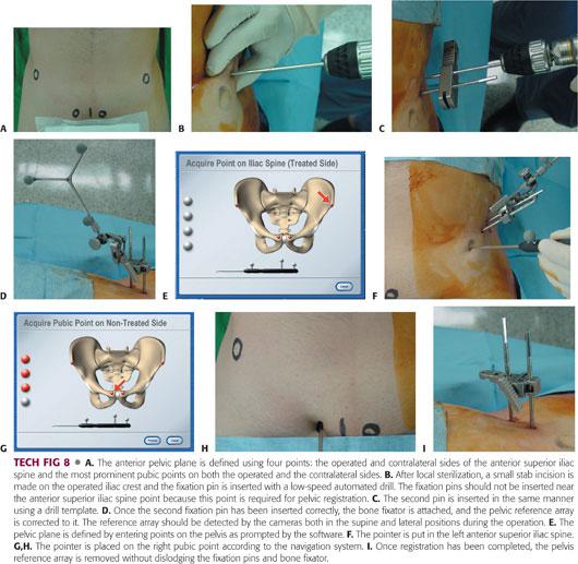
Once two pins have been inserted, the bone fixator and the pelvis reference array are attached (TECH FIG 8D).
The bone fixator should remain attached until the end of the entire navigation procedure.
The plane of the pelvis is defined by entering points on the pelvis according to the navigation software (TECH FIG 8E,F).
Bony landmarks of interest are the left and right anterior superior iliac spine and the most anterior parts of both pubic bones, which, in most patients, are the pelvic tubercles (TECH FIG 8G,H).
Once registration has been completed, the pelvis reference array is removed without dislodging the fixation pins and bone fixator (TECH FIG 8I).
The reference array is stored in a sterile location until it is reattached.
Repositioning the Patient
When the pelvis registration procedure is finished, the patient is moved into the lateral decubitus position, and the surgical area is sterilized and draped thoroughly (TECH FIG 9).
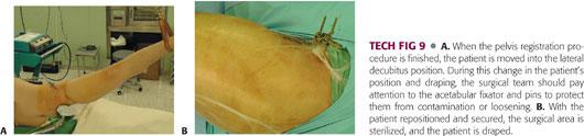
During draping, the surgical team should pay attention to the acetabular fixator and pins to protect against contamination or loosening.
Acquiring Acetabular Landmarks
The skin is incised in a routine manner and the acetabulum is exposed.
Multiple landmark acquisition is used to register the cotyloid fossa and acetabular surface, including margins (TECH FIG 10A–D).
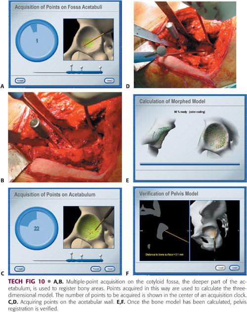
To begin multiple landmark acquisition, the tip of the pointer is touched to the required structure and pivoted slightly.
Points are acquired by sliding the pointer tip along the defined structure.
Once the bone model has been calculated in the navigation monitor, pelvis registration should be verified immediately (TECH FIG 10E,F).
Inserting the Acetabular Cup
To insert the cup at the desired angle, the bone must be reamed at the same angle as the planned cup (TECH FIG 11A).
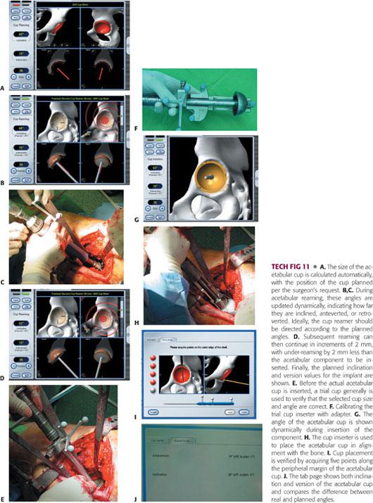
The acetabulum is initially reamed with an 8-mm diameter reamer, which is smaller than the planned cup size (TECH FIG 11B,C).
Subsequent reaming can then continue in increments of 2 mm.
The planned inclination and version values for the implant are shown during reaming, and the values are updated dynamically (TECH FIG 11D).
Once the reamer has been navigated to the planned position and reaming has been completed, a trial cup generally is used to confirm that the selected cup size is correct (TECH FIG 11E).
The cup is calibrated with the trial cup or cup inserted (TECH FIG 11F,G).
The cup inserter is navigated to the planned position, and the cup is inserted according to the manufacturer’s recommendations until correct cup placement has been achieved (TECH FIG 11H).
The cup should be positioned using the anatomy as a reference and aligned with the bone.
To verify cup position, the pointer is used to acquire four or five points along the margin of the cup (TECH FIG 11I).
The navigation screen shows various values for the position of the cup implant (TECH FIG 11J).
Once cup verification has been finished, the pelvic reference array, bone fixator, and two pins are removed, and femoral preparation proceeds.
Acquiring Femoral Landmarks
For femoral pin insertion, two pins are inserted to the lesser trochanteric area (TECH FIG 12A).
The location of the pins varies. They can be inserted into the proximal diaphyseal area, but the lesser trochanteric area is more comfortable and requires a smaller incision.
Once two pins have been inserted, the bone fixator and femoral reference array are attached (TECH FIG 12B).
Before starting registration, as many osteophytes are removed as possible because the presence of osteophytes will affect the femoral notching calculation.
The first step in femur registration is marking of the medial and lateral epicondyles using a sterile pointer (TECH FIG 12C,D). The pointer then is held to the piriformis fossa and head–neck junction (TECH FIG 12E,F).
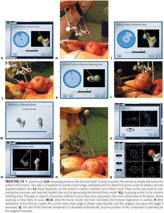
To acquire femoral head points, the pointer is slid across the surface of the bone following the navigator’s direction (TECH FIG 12G,H).
Once the femoral head points have been acquired, points are acquired on the anterior, superior, posterior, and inferior neck in sequence (TECH FIG 12I,J).
Finally, it is necessary to ensure that there are sufficient points in the most critical area of the bone where notching is more likely to occur (TECH FIG 12K,L).
Once registration has been accomplished, a three-dimensional bone model is made on the navigation monitor based on the points acquired (TECH FIG 12M).
Once the bone model has been made, registration of the femur is verified (TECH FIG 12N,O).
The current neck–shaft angle (ie, varus or valgus, anteversion or retroversion) and calculated inner diameter of the head implant (head size) are shown automatically with images on the navigation screen (TECH FIG 12P).
The software selects the implant size and angle to determine the smallest possible implant that will not cause femoral notching (TECH FIG 12Q).
If necessary, the surgeon adjusts the implant size manually according to the preoperative planning and matches the size with the acetabular component.
Femoral Preparation Using Navigation
Once navigation planning for head implantation has been finished, the drill guide pin is inserted into the femoral head using navigation.
The guide pin is moved along the varus–valgus axis and along the antegrade–retrograde axis. The drill guide pin is then relocated to the entry point selected following the navigation system so that it will not result in femoral notching (TECH FIG 13A,B).
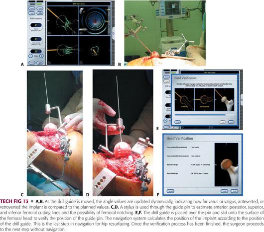
Once the final adjustment has been made, drilling begins via the centering guide pin and femoral notching is rechecked using a stylus (TECH FIG 13C,D).
Once the hole is successfully drilled and the implant positioned, femoral verification is undertaken (TECH FIG 13E,F).
The remaining procedures for femoral component are done in the same manner as those for conventional resurfacing procedures described earlier.
PEARLS AND PITFALLS | |
Acetabular position |
|
| |
| |
| |
Prevent femoral notching |
|
| |
| |
| |
| |
| |
Femoral component seating |
|
| |
Femoral side first |
|
| |
| |
| |
Acetabular side first |
|
| |
| |


POSTOPERATIVE CARE
 The patient receives a second-generation cephalosporin 1 hour before the operation starts and for 36 to 48 hours postsurgery.
 An antithromboembolic stocking and pneumatic pump is applied immediately after the operation to prevent deep vein thrombosis (DVT) and permit mobilization on the first day after the operation.
 Low-molecular-weight heparin or indirect factor Xa inhibitor can be administered for medical prevention of DVT and pulmonary embolism (depends on DVT prevalence in each country).
 Various protocols for rehabilitation may be followed:
We continue partial weight bearing with crutches for 4 to 6 weeks to allow initial bony ingrowth on the acetabular side and to allow the patient to regain normal gait and balance.
To allow femoral remodeling around the neck area, we usually recommend that the patient use a cane until the end of the second month after the operation, after which full weight bearing is permitted. Light sports activity may begin no sooner than 3 months after the operation, after which the patient may even squat on the floor.
Patients are allowed to ride in a car as a passenger, drive a car, sleep on their side, or engage in any activities if able and so desired.
Regular sports activities are allowed after 6 months.
OUTCOMES
 Many authors have reported long-term results of metal-on-metal hip resurfacing arthroplasty. Treacy et al26 reported a 95.5% survival rate at 10 years postoperatively in 144 consecutive patients, using the Birmingham hip resurfacing system (Smith & Nephew, Memphis, TN). Amstutz et al.3 reported a survival rate of 93.9% at 5 years and 88.5% at 10 years postoperatively in 100 patients, using the Conserve Plus system (Wright Medical Technology, Memphis, TN). They also reported that the 10-year survival rates were 95.6% for those with a femoral component size of greater than 46 mm, 83.8% for 44 mm and 46 mm, and 78.9% for 42 mm or smaller. Gross et al9 reported an 11-year survivorship rate of 93% using the hybrid Corin Cormet 2000 system (Corin Medical, Cirencester, United Kingdom).
 Mont et al19 reported the results of metal-on-metal hip resurfacing for treatment of osteonecrosis of the femoral head in 42 hips with mean of 41 months follow-up. At the time of the final follow-up, the survival rate was 94.5% for patients with osteonecrosis and 95.2% for patients with osteoarthritis.
 Amstutz and Le Duff2 reported no difference in survivorship between the osteonecrosis group and the control group after adjusting for head size, body mass index, and defect size. The 8-year survival rate for the osteonecrosis group was 93.9% and the control group 93.4%.
 Daniel et al6 reported on the results of metal-on-metal resurfacing in patients younger than 55 years with hip osteoarthritis.
Four hundred forty-six resurfacings were performed in 384 patients, with a maximum follow-up of 8.2 years (mean 3.3 years).
Out of 440 hips, there was only one failure (0.02%), giving a survival rate of 99.8%.
Thirty-one percent of the men with unilateral resurfacings and 28% with bilateral resurfacings could do heavy or moderately heavy jobs; 92% of men with unilateral resurfacings and 87% of the whole group could participate in leisure-time sports activity.
 Yoo et al30 prospectively investigated the effect of resurfacing arthroplasty on the bone mineral density (BMD) of the femur by comparing 50 patients with hip resurfacing to 50 patients with uncemented THA.
The resurfacing patients demonstrated BMD loss of 2.6% in Gruen zone 1 and 0.6% in zone 7, whereas the THA patients had BMD loss of 7.8% in Gruen zone 1 and 7.7% in zone 7 at 1 year after surgery.
On the acetabular side, the resurfacing patients demonstrated BMD loss of 8% in Delee and Charnley zone 1 and 17.5% in zone 2, whereas the THA patients had BMD loss of 9.8% in zone 1 and 22.3% in zone 2.
 Hip resurfacing system transfers load to the proximal femur in a more physiologic manner than long-stem devices, and it may prevent stress shielding and preserves the bone stock of the proximal femur.24
 Cooke et al5 reported that bone density of the femoral neck following hip resurfacing appears to decrease at 6 weeks and 3 months, returned to preoperative levels at 1 year, and was maintained at 3 years.
 Technetium 99m (Tc 99m) bone scan/single photon-emission computed tomography, microangiography with microcomputer tomography revealed that the intraosseous vascular network blood supply to the femoral head is maintained after hip resurfacing even if division of the deep branch of the medial femoral circumflex artery occurs during a posterior approach.25 Forrest et al8 suggested that femoral head viability after hip resurfacing can be evaluated with fluoride positron emission tomography. Nasser and Beaulé20 recommended directing the reamer superolaterally and staying as close as possible to the inferomedial neck because damage to the retinacular vessels can occur without penetrating the femoral neck.
 Shimmin and Back23 carried out a national review of fractures associated with hip resurfacing systems implanted between 1999 and 2003 in Australia.
Eighty-nine surgeons inserted the Birmingham hip resurfacing system in 3497 cases.
Fracture of the neck of the femur occurred in 50 patients with an incidence rate of 1.46%.
• The relative risk of fracture was higher for women than for men.
• The mean time to fracture was 15.4 weeks and it was often preceded by a prodromal phase of pain and limping.
• Significant varus placement of the femoral component, intraoperative notching of the femoral component, and technical problems were the common risk factors in 85% of cases.
 McBryde et al17 reported that although female patients may initially appear to have a greater risk for the need for revision, this increased risk is related to differences in the femoral component size and thus indirectly relates to sex.
 Amstutz et al1 presented their experience with femoral neck fractures that occurred after metal-on-metal hybrid surface arthroplasty.
In a series of 600 resurfacings, five femoral neck fractures occurred (incidence 0.83%).
• Four of the fractures occurred within the first 5 months after surgery.
• All five fractures were associated with structural or technical risk factors, which may have weakened the femoral neck.
 Low bone density increases the risk of femoral neck fracture following resurfacing.1
 Schmalzried et al22 reported that the outcomes of resurfacing are dependent on the preoperative characteristics of the proximal femur; patients with higher grade hips (those with earlier stage disease) have better outcomes.
 In cases of failed joint-preserving procedures such as core decompression or vascularized fibular grafting for osteonecrosis of the femoral head, hip resurfacing arthroplasty may play a role as a salvage operation.4
 Impingement between the acetabular cup and the femoral neck after hip resurfacing occurred mainly at the superior aspect of the femoral neck with an incidence rate between 6.3% and 22%.10,29 However, most patients did not have symptoms affecting implant stability.
 de Steiger et al7 reported that articular surface replacement (ASR, DePuy, Warsaw, IN) prostheses used in conventional hip arthroplasty and in hip resurfacing exhibited a greater revision rate compared with other prostheses. The cumulative revision rate of arthroplasties involving the ASR system at 5 years postoperatively was 10.9% compared with 4.0% for arthroplasties involving all other types of resurfacing prostheses.
 Kwon et al15 reported that asymptomatic pseudotumor after metal-on-metal hip resurfacing arthroplasty was associated with significantly higher cobalt and chromium levels and inferior functional scores in 4% of the cases they studied.
 Langton et al16 reported that in a multicenter study involving 4226 hips, the median chromium and cobalt concentrations in the failed group were significantly higher than in the control group. Survival analysis showed a failure rate in the patients with ASR of 9.8% at 5 years compared with less than 1% at 5 years for the Conserve Plus and 1.5% at 10 years for the Birmingham Hip Resurfacing systems.
 In 2008, there was a voluntary recall of the Durom acetabular component (Durom Cup, Zimmer, IN) because the instructions for use/surgical technique instructions were inadequate.
 In 2010, the Medicines and Healthcare Products Regulatory Agency in the United Kingdom recalled the ASR total hip system because of new unpublished data from the United Kingdom joint registry indicating that revision rates within 5 years were approximately 13%.27
COMPLICATIONS
 Femoral neck fracture
 Neck notching
 Neck narrowing (over 10% of normal width)
 Impingement between acetabular component and the femoral neck
 Femoral loosening12
 Femoral head collapse due to osteonecrosis
 Acetabular loosening
 Stem tip condensation
 Soft tissue reactions to metal ion
Adverse local tissue reaction/aseptic lymphocytic vasculitis–associated lesions
Metal hypersensitivity
Pseudotumor
 Metal ion release into the bloodstream
 Infection
 Femoral/sciatic nerve palsy
 DVT
DVT
 Dislocation
 Heterotopic ossification
 Spur formation
REFERENCES
1. Amstutz HC, Campbell PA, Le Duff MJ. Fracture of the neck of the femur after surface arthroplasty of the hip. J Bone Joint Surg Am 2004;86A:1874–1877.
2. Amstutz HC, Le Duff MJ. Hip resurfacing results for osteonecrosis are as good as for other etiologies at 2 to 12 years. Clin Orthop Relat Res 2010;468(2):375–381.
3. Amstutz HC, Le Duff MJ, Campbell PA, et al. Clinical and radiographic results of metal-on-metal hip resurfacing with a minimum ten-year follow-up. J Bone Joint Surg Am 2010;92(16):2663–2671.
4. Chun YS, Yoo MC, Kim KI, et al. Total Resurfacing arthroplasty after failed hip preserving procedures for osteonecrosis of the femoral head [abstract]. Abstract book of the 21st Annual Congress of the International Society for Technology in Arthroplasty (ISTA). Seoul, Korea, 2008.
5. Cooke NJ, Rodgers L, Rawlings D, et al. Bone density of the femoral neck following Birmingham hip resurfacing. Acta Orthop 2009;80(6):660–665.
6. Daniel J, Pysent PB, McMinn DJW. Metal-on-metal resurfacing of the hip in patients under the age of 55 years with osteoarthritis. J Bone Joint Surg Br 2004;86B:177–184.
7. de Steiger RN, Hang JR, Miller LN, et al. Five-year results of the ASR XL Acetabular System and the ASR Hip Resurfacing System: an analysis from the Australian Orthopaedic Association National Joint Replacement Registry. J Bone Joint Surg Am 2011;93(24): 2287–2293.
8. Forrest N, Welch A, Murray AD, et al. Femoral head viability after Birmingham resurfacing hip arthroplasty: assessment with use of [18F] fluoride positron emission tomography. J Bone Joint Surg Am 2006;88(suppl 3):84–89.
9. Gross TP, Liu F, Webb LA. Clinical outcome of the metal-on-metal hybrid Corin Cormet 2000 hip resurfacing system: an up to 11-year follow-up study. J Arthroplasty 2012;27(4):533–538.
10. Gruen TA, Le Duff MJ, Wisk LE, et al. Prevalence and clinical relevance of radiographic signs of impingement in metal-on-metal hybrid hip resurfacing. J Bone Joint Surg Am 2011;93(16):1519–1526.
11. Hardinge K. The direct lateral approach to the hip. J Bone Joint Surg Br 1982;64B:17–18.
12. Howie DW, Cornish BC, Vernon-Roberts B. Resurfacing hip arthroplasty. Classification of loosening and the role of prosthetic wear particles. Clin Orthop Relat Res 1990;255:144–159.
13. Howie DW, Cornish BC, Vernon-Roberts B. The viability of the femoral head after resurfacing hip arthroplasty in humans. Clin Orthop Relat Res 1993;291:171–184.
14. Kim KI, Yoo MC, Cho YJ, et al. Comparison of results of resurfacing arthroplasty performed using a navigation system and conventional technique. Abstract book of the 21st Annual Congress of the International Society for Technology in Arthroplasty (ISTA). Seoul, Korea, 2008.
15. Kwon YM, Ostlere SJ, McLardy-Smith P, et al. “Asymptomatic” pseudotumors after metal-on-metal hip resurfacing arthroplasty: prevalence and metal ion study. J Arthroplasty 2011;26(4):511–518.
16. Langton DJ, Joyce TJ, Jameson SS, et al. Adverse reaction to metal debris following hip resurfacing: the influence of component type, orientation and volumetric wear. J Bone Joint Surg Br 2011;93(2):164–171.
17. McBryde CW, Theivendran K, Thomas AM, et al. The influence of head size and sex on the outcome of Birmingham hip resurfacing. J Bone Joint Surg Am 2010;92(1):105–112.
18. McMinn D, Treacy R, Lin K, et al. Metal on metal surface replacement of the hip: experience of the McMinn prosthesis. Clin Orthop Relat Res 1996;329(suppl):S89–S98.
19. Mont MA, Seyler TM, Marker DR, et al. Use of mental-on-metal total hip resurfacing for the treatment of osteonecrosis of the femoral head. J Bone Joint Surg Am 2006;88:90–97.
20. Nasser AB, Beaulé PE. Femoral head vascularity and hip resurfacing. In: Amstutz HC, ed. Hip Resurfacing Principles, Indications, Technique and Results. Philadelphia: Saunders Elsevier, 2008:17–22.
21. Ramesh M, O’Byrne JM, McCarthy N, et al. Damage to the superior gluteal nerve after the Hardinge approach to the hip. J Bone Joint Surg Br 1996;78B:903–906.
22. Schmalzried TP, Silva M, de la Rosa M, et al. Optimizing patient selection and outcomes with total hip resurfacing. Clin Orthop Relat Res 2005;441:200–204.
23. Shimmin AJ, Back D. Femoral neck fractures following Birmingham hip resurfacing. A national review of 50 cases. J Bone Joint Surg Br 2005;87B:463–464.
24. Sugano N. Femoral DEXA studies in hip arthroplasty. In: McMinn DJW, Modern Hip Resurfacing. London: Springer-Verlag, 2009: 131–133.
25. Sugano N, Nishii T, Hananouchi T. Femoral head blood supply studies. In: McMinn DJW, Modern Hip Resurfacing. London: Springer-Verlag, 2009: 125–127.
26. Treacy RB, McBryde CW, Shears E, et al. Birmingham hip resurfacing: a minimum follow-up of ten years. J Bone Joint Surg Br, 2011; 93(1):27–33.
27. U.S. Food and Drug Administration. Recalls. Available at: http://www.fda.gov/medicaldevices/productsandmedicalprocedures/implantsandprosthetics/metalonmetalhipimplants/ucm241770.htm. Accessed July 2, 2014.
28. Wagner H. Surface replacement arthroplasty of the hip. Clin Orthop Relat Res 1978;134: 102–130.
29. Yoo MC, Cho YJ, Chun YS, et al. Impingement between the acetabular cup and the femoral neck after hip resurfacing arthroplasty. J Bone Joint Surg Am 2011;93(suppl 2):99–106.
30. Yoo MC, Cho YJ, Kim KI, et al. Changes in BMD in the proximal femur after cementless total hip arthroplasty and resurfacing arthroplasty. Prospective, longitudinal, comparative study. J Korean Orthop Assoc 2006;41:212–219.
31. Yoo MC, Cho YJ, Kim KI, et al. Resurfacing arthroplasty in osteonecrosis of the femoral head [abstract]. Abstract book of the 23rd World Congress of the SICOT/SIROT. Istanbul, Turkey, 2005.
< div class='tao-gold-member'>


