This article presents a comprehensive overview of generating a digital Patient-Specific Anatomic Reconstruction (PSAR) model of the craniofacial complex as the foundation for a more objective surgical planning platform. The technique explores fusing the patient’s 3D radiograph with the corresponding high-precision 3D surface image within a biomechanical context. As taking 3D radiographs has been common practice for many years, this article describes various approaches to 3D surface imaging and the importance of achieving high-precision anatomical results to simulate surgical outcomes that can be measured and quantified. With the PSAR model readily available for facial assessment and virtual surgery, the advantages of this surgical planning technique are discussed.
A patient-centric surgical planning paradigm
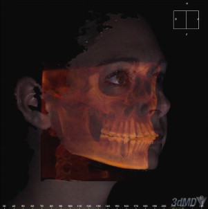
To achieve the best possible outcomes in facial cosmetic and reconstructive surgery, many clinicians are starting to embrace the use of powerful software tools that enable them to plan surgeries in a digital three-dimensional (3D) environment. The foundation of these tools is based on the patient’s unique anatomic model that fuses the patient’s 3D soft tissue surface with the underlying 3D skeletal structure ( Fig. 1 ). Although morphing a 3D surface to generate a desired result is generally accepted in the animation and character modeling world, true surgical planning requires that the software tool incorporate a firm understanding of the various anatomic components, their relative positions to one another, and the biomechanical relationships within the craniofacial complex.
Significant technological advances in the areas of computing, 3D imaging, and the Internet in the last 10 years, in combination with the adoption of 3D patient imaging protocols, are starting to push a next-generation, truly patient-centric care paradigm. With a patient-specific anatomic model that fuses the patient’s computed tomography (CT)/cone beam CT (CBCT), magnetic resonance imaging (MRI), and surface images from a single point in time, treatment planning for both the physician and patient becomes clear and understandable. Moreover, the proliferation of Web-based applications increases availability and decreases costs, enabling the virtual patient to be studied and improved treatment protocols to be developed.
Although the use of virtual anatomic reality in surgical planning can improve precision and reduce complications, it also promotes a larger health community goal of improving overall surgical results. Correctly planning and accurately simulating surgical outcome is paramount in facial surgery and the tools used should:
- 1.
Provide a patient treatment plan to achieve the desired result
- 2.
Give the patient a reasonable preview and understanding of the outcome
- 3.
Serve as a communication tool among multiple specialists (eg, orthodontists, surgeons) on the treatment team.
At the center of this approach is the true digital patient or “patient-specific anatomic reconstruction” (PSAR). The PSAR is not just a series of 3D images or traditional photographs/radiographs available in a file to view separately, it is an anatomically accurate record in which all of the patient’s 3D images (ie, CT/CBCT, MRI, facial surface images, teeth and so forth) are superimposed into 1 valid 3D structure and combined with the relevant biomechanical properties. This process, resulting in a single dataset from the combination of relevant information from 2 or more independent datasets, is called image fusion.
Strategies for 3d facial image fusion
When treating the face from a maxillofacial perspective, multiple imaging modalities are required to produce an accurate PSAR model of the patient. Depending on treatment, there is typically a protocol defined that requires a series of 3D images (in 1 or several different modalities) to be taken at specific points in time throughout the treatment cycle. The imaging modalities currently relevant to the maxillofacial region include:
- 1.
Traditional CT or the less invasive CBCT
- 2.
3D facial surface imaging (extraoral)
- 3.
3D dental study model surface scanning (intraoral).
Most commonly, the primary modality is CT/CBCT, to which other datasets are fused. Imaging technologies are emerging that may become important secondary modalities to which CBCT datasets may be fused, including :
- 1.
Ultrasound to document airway function
- 2.
MRI to isolate muscle and generate a basic facial surface image (Takács and colleagues, 2004)
- 3.
3D optical intraoral scanners to replace the dental impression technique and/or scanning physical study models
- 4.
Dynamic facial (four-dimensional [4D]) surface imaging to record facial movement and expression
- 5.
Positron emission tomography (PET).
The importance of the 3D surface image in surgical planning
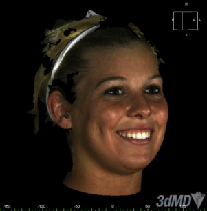
The face is the foundation for communications and interaction with the world, and thus patients are concerned with the effect a treatment might have on their appearance. This awareness is placing more emphasis on the importance of accurately documenting the patient’s external facial features and characteristics before treatment, and then using this as a basis to plan treatment and monitor progress throughout treatment. Although a series of photographs has been used traditionally for this function, the limitations of a 2D medium significantly reduce the ability to objectively quantify treatment results for patients. How patients sees themselves in photographs may be totally different than how a clinician sees the patient in the same photograph irrespective of the lack of 3D reality ( Fig. 2 ).
With a highly accurate 3D surface image of the patient’s face, this debate becomes objective because the treating physician can measure the geometric shape changes that resulted from treatment and/or growth (ie, the effects of a mandibular advancement, a palate expander, cleft repair, and so forth). The need for quantification of this effect and the minimizing of subjectivity is fueling the adoption of enabling technologies. Because of the exposure risks associated with the production of 3D images using ionizing radiation, noninvasive modalities and techniques are being investigated for incorporating 3D data into a patient’s PSAR. Optics-based 3D surface imaging systems are available to noninvasively capture anatomically precise 3D facial images of the patient. Not only can a patient’s surface image be taken before and after treatment in conjunction with the CT/CBCT images, the clinician has the option to image the patient as often as required depending on the treatment protocol. Soft tissue only procedures can be planned and monitored only using the 3D surface imaging modality. Dental impressions can be taken producing physical study casts that can be digitized into an in-vivo 3D dental model for incorporation into the PSAR.
3d Surface imaging techniques
For surface 3D construction, a 3D surface image has 2 components, the geometry of the face and the color information, or texture map that is mathematically applied to the shape information. The construction of 3D surface images involves 3 steps:
- 1.
3D surface capture. There are 2 basic 3D surface imaging approaches. One is laser based and the other is optics based. For human form imaging, the optics-based approach has been implemented as structured light, moiré fringe projection, and stereo photogrammetric techniques.
- 2.
Modeling. This stage incorporates sophisticated algorithms to mathematically describe the physical properties of an object. The modeled object is typically visualized as wireframe (or polygonal mesh), made up of triangles or polygons. The continuity of area between the polygons is filled in by the recruitment of surface pixels from the associated surface plane to generate a surface image or a texture map.
- 3.
Rendering. If the 3D surface imaging system captures surface color information, at this stage the pixels are provided with values reflecting color texture and depth to generate into a lifelike 3D object viewed on the computer screen.
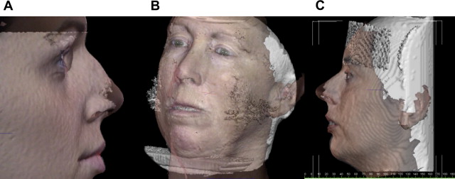
There are several potential advantages of registering anatomically accurate 3D facial surface images to CT/CBCT datasets ( Fig. 3 A–C).
- •
Surface images may correct for CBCT surface artifacts caused by patient movement (ie, swallowing, breathing, head movement, and so forth) because CBCT scans can take from 5 to 70 seconds depending on the manufacture of the CBCT unit and the imaging protocol;
- •
Independently acquired surface images compensate for soft tissue compression from upright CBCT device stabilization aids (ie, chin rest, forehead restraint, and so forth);
- •
Surface images may also the eliminate soft tissue draping from supine CBCT devices;
- •
Surface images may supplement missing anatomic data (ie, nose, chin, and so forth);
- •
Surface images may provide a more accurate representation of the draping soft tissue that reflects the patient’s natural head position for condition assessment and treatment planning.
In relation to surface 3D construction, a surface image has 2 components: the geometry of the face and the color information, or texture map that is mathematically applied to the shape information. Both are required for a realistic result that is also accurate.
There are 2 basic 3D surface imaging approaches. One is laser based and the other is optics based.
Laser-based Surface Imaging
In its basic form, a laser scanner calculates the coordinate of each point on the surface of the target by measuring the time it takes for a projected light ray to return to a sensor. To improve efficiency, more complex patterns are projected, such as a light stripe. This technology of scanning the face with a laser is based on projecting a known pattern of light to infer an object’s topography. This light can be in the form of a single bright light source; however, a light stripe is more commonly used. As an object is illuminated it is viewed by an offset camera. Changes in the image of the light stripe correspond with the topography of the object, and these distortions are recorded to produce 3D data for the object. Practically, the light may remain fixed and the object move or vice versa. Geometry triangulation algorithms allow depth information to be calculated, coordinates of the facial surface can be derived, and computer software can be used to create a 3D model of the object. Changes in dimensions between repeated scans or changes as a result of treatment are often shown by color differentiation or color maps. Several devices are currently commercially available ( Table 1 ).
| Name | Model | Manufacturer | Web Address |
|---|---|---|---|
| FastSCAN | Cobra/Scorpion | Polhemus, Colchester, VT | http://www.polhemus.com |
| Head & Face Color 3D Scanner | PX | Cyberware, Inc., Monterey, CA | http://www.cyberware.com |
| Minolta Vivid | 910 | Konica Minolta Sensing Americas, Inc., Ramsey, NJ | http://www.konicaminolta.com |
There are some disadvantages to this approach:
- •
The digitization process requires the subject to remain still for a period of up to 30 seconds or more while the laser vertically scans the subject’s face. Although the 3D model generated might be accurate on a band-by-band basis, a single human face comprises thousands of bands from top to bottom and each band is taken sequentially. Although this amount of time works adequately for inanimate objects in industrial applications, such as reverse engineering, quality inspection, and prototyping, laser technologies have proved difficult to use on conscious subjects, especially children. Movement increases the likelihood of distortion, noise, and voids of the scanned image.
- •
Because the process involves the use of a laser, there are safety considerations related to the exposure of the eyes.
- •
The output can be noisy thus requiring additional processing to treat noise, outliers, and deficiencies in the generated geometry.
- •
The lack of soft tissue surface color texture information has also been highlighted as a possible drawback, because this results in potential difficulties in the identification of landmarks that are dependent on surface color.
Several investigators have applied this approach, particularly for the assessment of facial asymmetry, treatment outcome, and relapse, and reported precision of the laser scanning device to be approximately 0.5 mm on inanimate objects such as O’Grady and Antonyshyn’s plaster head model; however, others have reported that many measurements were unreliable (errors higher than 1.5 mm). In addition, patients are scanned with their eyes closed, which may interfere with the natural facial expression and any landmarks placed around the eyes. With scan durations of 10 seconds or more, such geometry inaccuracies are likely attributed to software attempts to compensate for movement during the scanning process.
Optics-based Imaging
For human form imaging, the optics-based approach has been implemented as structured light, moiré fringe projection, and stereo photogrammetric techniques. Several systems have been commercially produced ( Table 2 ).
| Name | Type | Manufacturer | Web Address |
|---|---|---|---|
| Rainbow 3D | SL | Genex Technologies, Inc., Bethesda, MD | http://www.genextech.com |
| 3dMDface/3dMDcranial Systems | SP | 3dMD, Atlanta, GA | http://www.3dmd.com/3dmdface.html http://www.3dmd.com/3dmdcranial.html |
| FaceSCAN 3D | MFP | 3D-shape GmbH, Erlangen, Germany | http://www.3d-shape.com |
| FaceSnatcher | SL | Eyetronics NV Leuven, Belgium | http://www.eyetronics.com |
Structured light
This is an optical technique that projects structured light patterns (usually white light), such as grids, dots, or stripes, onto the subject. Next, a single image of the subject and the projected pattern are acquired by a digital camera within the system. The reconstruction software is initially calibrated with the spatial position of the camera and the specifics of the projected light pattern. The distortion of the light pattern is then analyzed by the system’s software and the 3D shape is inferred from the scale of the visible distortion. Color texture information is inherently registered with the xyz coordinate information. Although technically straightforward, this approach suffers from several problems including:
- •
Limitations in accurately capturing occluded areas and steep contours inherent in a single view point of the human face.
- •
Inability to generate an accurate 3D model of a human subject’s face from ear to ear (180°). To image the complete craniofacial complex comprising both left and right profiles, a system with at least 2 imaging viewpoints must be used to eliminate the challenges associated with occlusions in the structure of the face, particularly the nasal region. Because of the nature of the pattern projected, these images have to be taken in sequence to avoid pattern interference (ie, a grid pattern from one viewpoint overlapping with a grid pattern from another angle). Sequential image capture extends the acquisition duration because of the time lag, which, for living human subjects, can be detrimental to the resulting data accuracy. This deficiency has reduced the application of this technique in health care.
Because of the inherent challenges for achieving accuracy, there are limited studies on the application of this technique to facial imaging in quantification of facial soft tissue changes after surgery, craniofacial assessment, and facial swelling. Mean accuracy has been reported to be approximately 1.25%, with reproducibility being 3.27%.
Moiré fringe projection
This optics-based technique projects a moiré fringe pattern onto the subject and the surface shape is calculated by analyzing the interference between projected patterns from a known point of observation. Moiré fringing is an improvement compared with simple structured light because the pattern used for reconstruction is inherently more granular or dense. In addition, more of the facial profile, especially the topology of the nose, is captured. To capture all of the facial features, up to 5 separate observations are required. Moiré 3D reconstruction suffers the same limitations as structured light because the data acquisition is interspersed with processing and has several other shortcomings including:
- •
It significantly increases the time taken to acquire the image. Even with the use of mirrors, each angle has to be acquired separately to avoid unwanted interference across images. In addition, the type of projectors used to project an accurate fringe requires a significant warm-up time and have a residual latency when powering down in comparison with photographic flash.
- •
Motion artifacts are inherent and require the use of special compensation algorithms.
- •
Careful control of lighting is required to avoid any stray spectral interference with the moiré patterns.
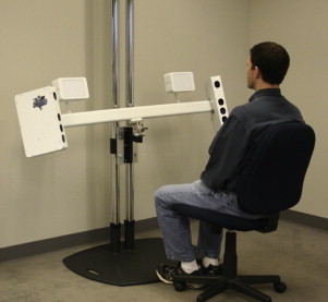
Although industrial engineering tends to uses moiré fringe projection for scanning inanimate objects, application of this methodology to facial imaging has been mainly limited to laboratory conditions for the assessment of age-related skin changes, facial asymmetry, postoperative facial changes, and normal morphology. To date, there has been little published on accuracy validation from a live patient perspective. The general issue with moiré fringe approach for live human subjects is common with other techniques requiring the projection of precalibrated structured light techniques: speed of capture. Although it has been possible to produce limited research in strictly supervised laboratory conditions, this can often entail the taking of several images of the subject until a workable model is captured. Such a workflow tends to inhibit larger data collection exercises in normal clinical environments because the workflow entailed obstructs the regular business of the clinic ( Fig. 4 ).
Related posts:
 Foreword
 3D and the Next Dimension for Facial Plastic Surgery
Assessment of Rhinoplasty Techniques by Overlay of Before-and-After 3D Images
3D and the Next Dimension for Facial Plastic Surgery
Assessment of Rhinoplasty Techniques by Overlay of Before-and-After 3D Images
 3D Analysis of Dentofacial Deformities: A New Model for Clinical Application
 Teaching 3D Sculpting to Facial Plastic Surgeons
 3D Volume Assessment Techniques and Computer-Aided Design and Manufacturing for Preoperative Fabrication of Implants in Head and Neck Reconstruction
Stay updated, free articles. Join our Telegram channel

Full access? Get Clinical Tree


