Recent advancements in computer technologies have propelled the development of 3D imaging systems. 3D surface-imaging is taking surgeons to a new level of communication with patients; moreover, it provides quick and standardized image documentation. This article recounts the chronologic evolution of 3D surface imaging, and summarizes the current status of today’s facial surface capturing technology. This article also discusses current 3D surface imaging hardware and software, and their different techniques, technologies, and scientific validation, which provides surgeons with the background information necessary for evaluating the systems and knowledge about the systems they might incorporate into their own practice.
History of three-dimensional surface imaging systems
Introduction of Systems
The three-dimensional (3D) quantitative analysis of facial morphology is vitally important in plastic and reconstructive surgery. Past attempts to measure the complexities of the human face include stereophotogrammetry, image subtraction technique, moiré topography, liquid crystal scanning, light luminance scanning, laser scanning, stereolithography, and video systems. A few of these have used instruments that provided 3D measurements with promising results, but only more recently have these instruments found a greater place in routine clinical use.
Stereophotogrammetry
Thalmaan made one of the first attempts to capture the 3D surface of the face in 1944. It was also the first attempt to use stereophotogrammetry in clinics. This technique was based on measurements from photographs. Thalmaan examined an adult with facial asymmetry and a baby with Pierre Robin syndrome. Images of the subject from two different views were taken and inserted into a plotting machine to draw 3D contour maps. In 1967, Burke and Beard improved on Thalmaan’s method by using simpler and less-expensive cameras. They improved and shortened the time-consuming method through applying a multiplex plotting system. Their method was applied to assess facial deformities (eg, cleft palate, cleft lip palate) in children and the growth spurt of soft tissue in the face, and to measure faces preoperatively and postoperatively. They expected that the modified method would allow a wider application of this technique to document facial deformations.
In 1995, Ras and colleagues concluded that stereophotogrammetry was an appropriate 3D registration method for quantifying and detecting development and changes in facial morphology. Deacon and colleagues greatly improved the stereophotogrammetric technique in 1999. They replaced the precalibrated metric cameras and film emulsion with low-cost charge coupled device (CCD) cameras, which offered the advantage of digitized image capture for 3D automatic analysis, drastically shortening the manual analysis of stereophotogrammetry.
Liquid Crystal Range Finder
In 1984, Inokuchi and colleagues developed the liquid-crystal rangefinder for recognizing facial deformities in three dimensions. This device was an imaging system that used gray-coded pattern projection to generate 3D images. The exposure time, approximately 1 second for a recording session, was considered advantageous over the 8 to 30 seconds of scanning time in laser systems; therefore, time-motion artifacts could be eliminated.
Laser Systems
Laser scanning systems have high resolution and are accurate. They have been widely used in anthropometric studies, and some have been applied in clinics. The first 3D laser system to be routinely used in a clinic was devised by Moss and colleagues in 1991 at the Department of Orthodontics at University College in London. They monitored the growth of children with facial deformities for more than a decade. Data acquisition took approximately 10 seconds, and its accuracy was ± 0.5 mm.
In 1993, Vannier and colleagues reported examination of the human head with an optical laser system consisting of six scanners. The acquisition process took less than a second for a 360° image, which was the shortest time among laser scanning systems. The system proved sensitive enough to detect subtle dimensional changes resulting from surgery, including postoperative edema and surface changes from facelift procedures, and it provided accurate and complete 3D coverage of the complex facial surface. In 1995, Cacou and colleagues were the first to combine electromyography and laser scanner technology to study facial muscle functions. Their system showed highly accurate measurements and was said to be suitable for monitoring changes during facial treatments. Accuracy and highly repeatable imagery improved over the years and was proven to produce accurate 3D images. Kohn and colleagues reported that most errors in the scanning process were in the location procedure of landmarks; therefore, Bush and Antonyshyn recommended setting up a standardized head position to attain an optimal laser image.
Subtraction Technique
In 1992, Neely and colleagues developed an image subtraction technique, wherein a black-and-white video camera captured the subject’s maximal facial movements, which were then analyzed by computer software. This technique was rapid and region-specific, and quantified the images objectively along a dimensional data scale. This method produced promising results, which were correlated with the House-Brackmann facial nerve grading system, illustrating facial functional deficit at measured distances.
Moiré Topography
Takasaki devised Moiré topography in 1970. Moiré is a French word for “watered,” describing the geometric design that results when a set of straight or curved lines is superposed onto another. This technique is based on the light interference theory, in which illumination through a grid creates contour lines on an object. Takasaki used moiré photographs to assess facial asymmetry and surface deformation during facial expression. Using this system in 1992, Inokuchi applied Moiré topography to probe the “Moiré Index,” a method to quantitatively assess facial movements and the severity of facial palsy. Yuen and colleagues reported in 1997 that this system was extremely time-consuming in the evaluation procedure.
Light Luminance
OSCAR (objective scaling of facial nerve function based on area analysis), developed in 1998 by Meier-Gallati and colleagues, was an objective scaling system of facial nerve function. It used a black-and-white camera to capture the variations of luminance produced by changes of facial expression and thereby assess dynamic facial asymmetry. This method proved to be objective, reproducible, fast, and simple to use; however, it allowed no absolute measurement of distances in the face.
Video Systems
In 1989, Caruso and colleagues attempted to assess 3D facial movements. Three video cameras (50 Hz), based on a 3D kinematic system (VICON, Oxford Metrics, Inc., Tampa, Florida), were used to collect the data. They showed the feasibility of obtaining 3D trajectories of lip and jaw landmarks during chewing movements.
In 1994, Ferrario and colleagues developed a videotaping system to quantify facial asymmetry. Standardized facial landmarks were collected by two 50-Hz cameras (ELITE system, BTS, Milan, Italy). These landmarks were automatically recognized. The x , y , and z coordinates were reconstructed and calculated with software (Laboratorio di Anatomia Funzionale dell’Apparato Stomatognatico, Milan, Italy). This study reported the feasibility of 3D quantification and the assessment of facial asymmetry.
In 1994, Paletz and colleagues devised one of the first video systems to access facial morphology and movements. This two-dimensional (2D) video assessment of facial movements studied trajectories of lip landmarks during a natural smile. They quantified the amplitude and direction of the landmarks in motion by using a 16-mm cine camera.
Trotman and colleagues showed a video analysis system in 1996, which provided data of facial movements in three dimensions. Facial motions were captured by three 60-Hz video cameras (Motion Analysis, Motion Analysis Corporation, Santa Rosa, California), whereupon 3D maximum motion amplitudes were calculated by a computer workstation (Sun Sparc, Sun Corporation, Palo Alto, California). This video-based tracking system showed impairment and habilitation of facial movements, determining which regions of the face show the greatest excursion during specific facial animation.
In 1997, Bajaj-Luthra and colleagues devised the maximal static response assay, a study using a 2D video system to focus on the quality and quantity of synkinetic movements in healthy faces. Here, facial movements with defined landmarks were recorded and analyzed through subtracting their position-in-repose image from images depicting their maximal motion. This system contributed to the fundamental knowledge of synkinesis in faces; however, it was capable only of 2D measurements.
However, assessing absolute measurements of facial movements was impossible. Frey and colleagues concentrated their efforts on quantitatively and qualitatively assessing facial movements in 1994 on a computer-assisted video system with four cameras (VICON, Video Systems, Inc., West Palm Beach, Florida). Three-dimensional facial landmark movements were calculated as a percent of reference distances. In 1999, Frey and colleagues improved the principle of the VICON video system through replacing three of four cameras with a simple mirror system. This innovation needed only one camera to capture 3D movements in the face and has been reported to be in clinical routine use ever since.
Recent developments in 3D surface imaging systems
Technological advances in the past 2 decades have made 3D surface imaging accessible to patient protocols; moreover, imaging management and 3D analysis and treatment planning software applications are being reengineered to handle and analyze these highly precise 3D data formats efficiently. Laser and optical-based surface imaging technologies have evolved and are widely used in the medical fields. Optical-based surface imaging technologies include structured light imaging and stereophotogrammetry imaging systems. The basic principles of structured light imaging and stereophotogrammetry imaging systems are described; particulars can vary depending on business focus from one manufacturer to another.
Laser Imaging Technology
Laser imaging acquires 3D data through scanning a laser beam (spot or stripe) across a target object. It normally uses a straightforward geometric calculation to determine the surface coordinates of the object. The object scatters the light, which is collected at a known triangulation distance from the laser. Through using trigonometry, the x , y , and z coordinates of a surface point are calculated.
Structured Light Technology
Structured light technology projects organized patterns of white light (grids, dots, or stripes) onto the surface of a target object while photographing the subject with a camera calibrated with the specifics of the projected light pattern. The distortion of the light pattern is captured and processed to generate the shape data and inherently register pertinent color and texture information. To generate an accurate 3D model, a two-viewpoint capture must be taken in sequence to avoid pattern interference.
Stereophotogrammetric Technologies
Stereophotogrammetric techniques take a sophisticated software approach based on the fundamental principle of taking two pictures of the same object to create a stereo pair, recording depth to generate a composite 3D model. The recorded pattern on the surface provides the stereo algorithms with the base information required to build accurate 3D geometry. Once the 3D geometry model has been produced, software maps the color and texture information onto the model. Two basic triangulation strategies exist for stereo photogrammetry: active and passive.
Active Stereophotogrammetric Technology
Active stereophotogrammetry deploys the projection of a focused random unstructured light pattern on the actual surface of the target object. It combines this pattern with the visible natural pattern of the object’s surface (if any) to give the stereo algorithms as much information as possible to generate a quality 3D geometry. No special external lighting conditions are needed for this technique, and it is resilient to the effects of ambient lighting.
Passive Stereophotogrammetric Technology
In contrast, passive stereophotogrammetry generates 3D geometry solely based on the natural patterns of the target object’s surface. High-resolution cameras are needed to ensure that enough surface detail is available to generate the 3D geometry. Care must be taken to avoid the effects of strong directional ambient light to avoid glare on the surface.
Current Status
Currently, the promising methods of 3D surface imaging are stereophotogrammetry (passive and active) and structured light. Five companies currently provide the most notable commercialized 3D imaging software and hardware that is sold and supported worldwide, and each offers different approaches toward 3D surface imaging techniques:
- •
3dMD ( www.3dmd.com ), based in London, United Kingdom, and Atlanta, Georgia
- •
Axis Three ( www.axisthree.com ), based in Belfast, Ireland
- •
Canfield ( www.canfield.com ), based in Fairfield, New Jersey
- •
Di3D ( www.di3d.com ), based in Glasgow, Scotland, United Kingdom
- •
Genex ( www.genextech.com ), based in Bethesda, Maryland
The following sections give an overview of these systems.
3dMD
3dMD History
The 3dMD company started in 1999 with the first delivery of a 3dMD system. 3dMD had already launched into the United States health care market and started to develop breast reconstruction imaging and cosmetic imaging technologies. Subsequently, it delivered 3dMD products to MD Anderson Cancer Center, Procter & Gamble, and the National Institutes of Health (NIH/NIDCR). Because of significant positive feedback from clinical users worldwide, which specified and validated its systems, it was able to launch the first four-dimensional (4D) motion capture version of the 3dMDface System in 2005. In 2007, it introduced the 3dMDvultus software application for 3D surface image fusion with CT and CBCT (cone beam CT), which is a lower radiation dose CT, compared with the conventional CT. Its hardware is smaller, and therefore easily fits into almost any clinical routine. At this moment, 3dMD is focusing on extending its 3dMDvultus software and refining its 4D motion technique. 3dMD reports that their 60-frame-per-second 4D face system with a two-viewpoint perspective is now in approximately 20 universities around the world that are focused on research in this field. Some published research is referenced on 3dMD’s Web site.
3dMD Technology
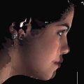
The 3dMDface System ( http://www.3dmd.com/3dmdface.html ) uses a hybrid of active and passive stereophotogrammetry for 3D surface imaging ( Fig. 1 ), wherein the software algorithms use a combination of the projected random pattern and the natural surface patterns, such as pores and freckles on the skin. This modular system consists of two pods, each of which contains one full color and two black-and-white machine vision cameras. Pictures are captured by light photography with industrial-grade cameras. The capture time is approximately 1.5 ms (1/650th of a second), limiting the risk of motion artifacts. The six simultaneous photographs of the face are rendered with professional personal computer equipment for approximately 30 seconds to reconstruct the 3D stereophotogrammetric picture (in the form of a .TSB file and any industry-standard 3D file format), to be viewed in the 3dMDvultus software program and other commercially available 3D software programs. The typical data file size of a 3dMD capture is approximately 20 MB. Advantages of the 3dMD system are ultra high speed capture (1.5 ms), eliminating errors caused by patient movement (ideal for children), ease of use, short calibration (<2 minutes), and a software platform that supports CT/CBCT initiatives, radiation-free planning, outcome simulation, and treatment follow-up. Most of the technique ensures high-quality geometry capturing, regardless of lighting conditions. Geometry accuracy is less than 0.2 mm root mean square or better. The 3dMDface System is designed to be compact and extremely robust. Many of these systems are regularly transported as standard airline luggage to remote locations and treatment facilities around the world. This robustness easily enables use at home in the practice or clinic.
According to the company, more than 1000 3D surface imaging units have been supplied around the world, and the 3dMDface System is exceptionally reliable. In the rare event of an operational issue, the company’s technicians can diagnose the problem remotely and rectify the situation within hours. The 3dMDvultus software simulates real-time soft tissue changes from the mass spring biomechanical model, based on long-term published scientific research.
3dMD Scientific Validation
At least four medical groups have validated the face and breast system so far.
In 2005, Aldridge and colleagues investigated the precision, error, and repeatability associated with anthropometric landmark coordinate data collected from the 3dMD system. Data collected from images with the 3dMDface System were highly repeatable and precise: the average error associated with the placement of landmarks was submillimeter. The investigators concluded that anthropometric data collected using the 3dMDface System are highly reliable.
In 2005 by Losken and colleagues validated the ability to qualitatively determine differences in shape, size, and contour of the breast. The relative difference between the measured volume and the calculated volume was approximately –2%, with a standard deviation of ± 13% to 16%. The coefficient of reproducibility for each reader was excellent, between 0.80 and 0.92. Surface measurement of nipple to notch showed the mean relative difference between the measured and calculated distances for raters was approximately –6%, with a standard deviation of ± 6% to 7%. They concluded that the ability to determine breast volume and surface measurements objectively with 3D imaging technology is now available with consistent and reproducible accuracy. Three-dimensional technology provides invaluable information, particularly in the longitudinal evaluation of results.
Maal and colleagues objectively evaluated treatment outcomes in oral and maxillofacial surgery via pretreatment and posttreatment 3D photographs of the patient’s face. Three-dimensional images and facial expressions were captured with Maxilim (Medicim NV, Mechelen, Belgium) and 3dMD (3dMD LLC, Atlanta, Georgia). They found a strong correlation between the results of hardware and software packages. The intraobserver and interobserver error for the reference-based registration method was found to be 1.2 and 1.0 mm, respectively, in the Maxilim software. No significant difference was found between the software packages that were used to perform surface-based registration.
In 2010, Lubbers and colleagues evaluated the handling of the 3dMD system in matters of data acquisition and analysis. They found the system to be very reliable, with a mean global error of 0.2 mm (range, 0.1–0.5 mm) for mannequin head measurements; neither the position of the head nor that of the camera influenced these parameters. They recommended the system for evaluation and documentation of the facial surface and suggested it could offer new opportunities in reconstructive surgery.
Related posts:
 Foreword
 3D and the Next Dimension for Facial Plastic Surgery
Assessment of Rhinoplasty Techniques by Overlay of Before-and-After 3D Images
3D and the Next Dimension for Facial Plastic Surgery
Assessment of Rhinoplasty Techniques by Overlay of Before-and-After 3D Images
 3D Analysis of Dentofacial Deformities: A New Model for Clinical Application
 Teaching 3D Sculpting to Facial Plastic Surgeons
 3D Volume Assessment Techniques and Computer-Aided Design and Manufacturing for Preoperative Fabrication of Implants in Head and Neck Reconstruction
Stay updated, free articles. Join our Telegram channel

Full access? Get Clinical Tree


