Chapter 17 Filler Injection of the Chin and Mandible Contour


10.1055/b-0040-178135

Chapter 17 Filler Injection of the Chin and Mandible Contour


Introduction


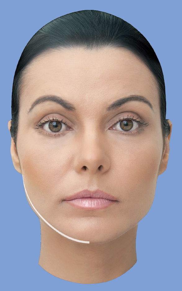
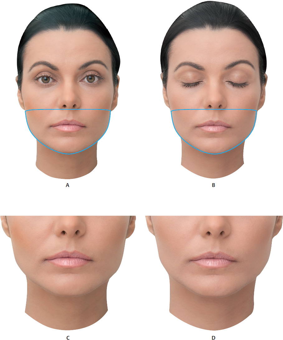
The contour of the lower third of the face is determined by the inferior edge of the mandible. A well-defined mandibular line, well-proportioned chin, and marked mandibular angle are all characteristics of a young and attractive face.


Filler injections with a more viscous and cohesive hyaluronic acid (HA) are an excellent option for remodeling the facial contour, making it possible to restore the volume lost over time, or to provide greater projection and contour for certain facial biotypes.


Three different face types are routinely def ined in the literature. The mesofacial type expresses balance, whereas the brachyfacial and dolichofacial types are at opposite ends of the biometric scale of the face. Mesofacial individuals have proportionate horizontal and vertical dimensions. Brachyfacial and dolichofacial ones have diametrically opposed characteristics; those with brachyfacial features have shorter and broader faces than those with dolichofacial features. It is important to remember that this classification is academic, so on a daily basis you will come across patients with intermediate characteristics between one biotype and another. 1 There is also a classification of the face with respect to the position of the mandible in relation to the cranium. Most people find class I profile attractive (normal or orthognathic mandible). The class II profile presents increased facial convexity because of a rare maxillary excess or mandibular deficiency. Normally, a maxilla with a good facial expression can be observed in individuals in whom the lower third of the face is deficient and the chin-neck line is short. Brachyfacial and class II individuals can benefit from filler injec tions in the lower third of the face. It is important to remember that odontological assessment is fundamental, as this procedure provides increase in volume, but does not correct occlusion alterations. 1 –. 4


The lower third of the face also differs between sexes. A man’s face is more contoured, and the mandibular line and angles are more defined. In women, however, two facial formats predominate:


  • Heart-shaped face: the malar and zygomatic regions are clearly apparent, and the inferior contour is delicate and not very expressive.


  • Angular face: the malar and zygomatic regions are significant, with an expressive inferior contour that has welldefined mandibular line and angle.


Anatomy


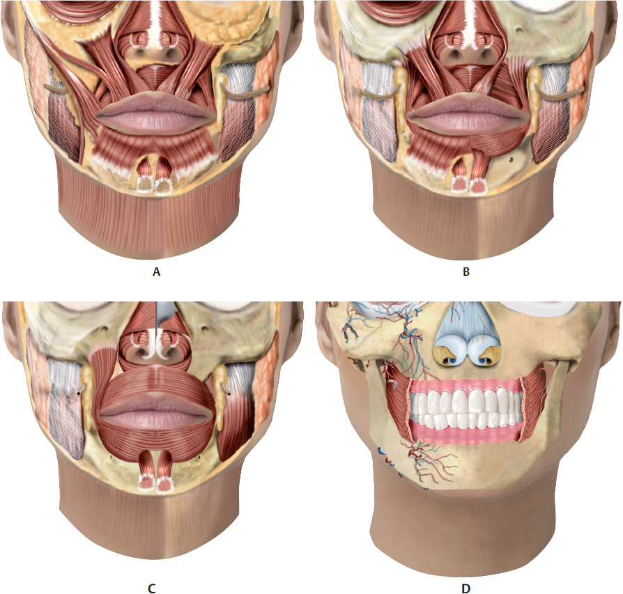
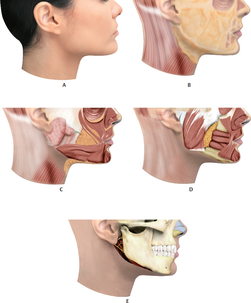
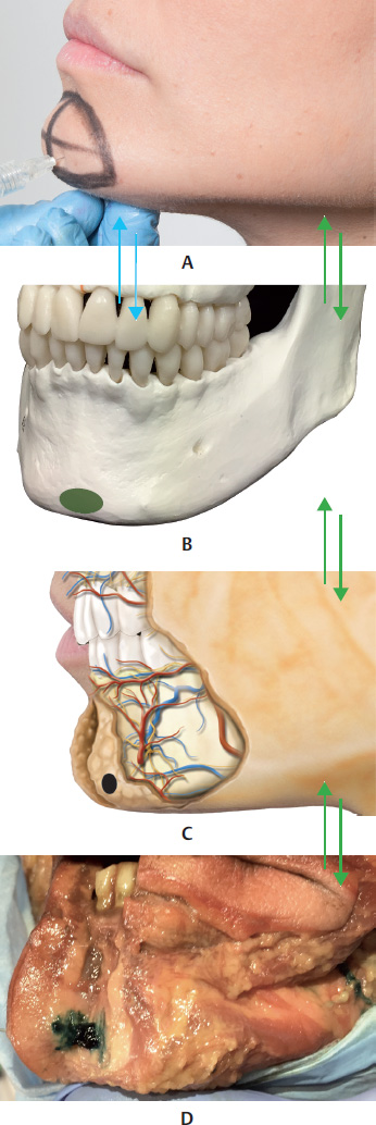
The mandible, or lower maxilla, consists of a horseshoe-shaped portion called the body, and two perpendicular portions, called the rami, which are joined to the body at almost a right angle. The external face is marked in the midline by a slight crest, which marks the mandibular symphysis or junction between the two pieces that make up the bone in a fetus. The space between the chin and the mandibular angle is called the mandibular line. 5


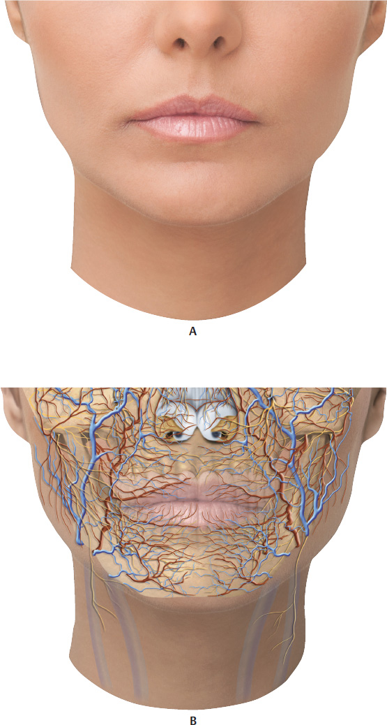
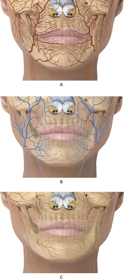
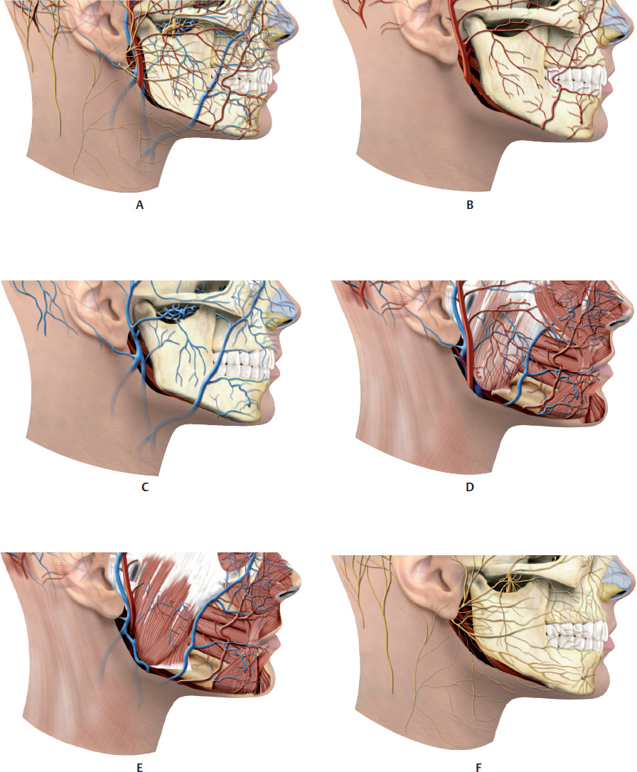
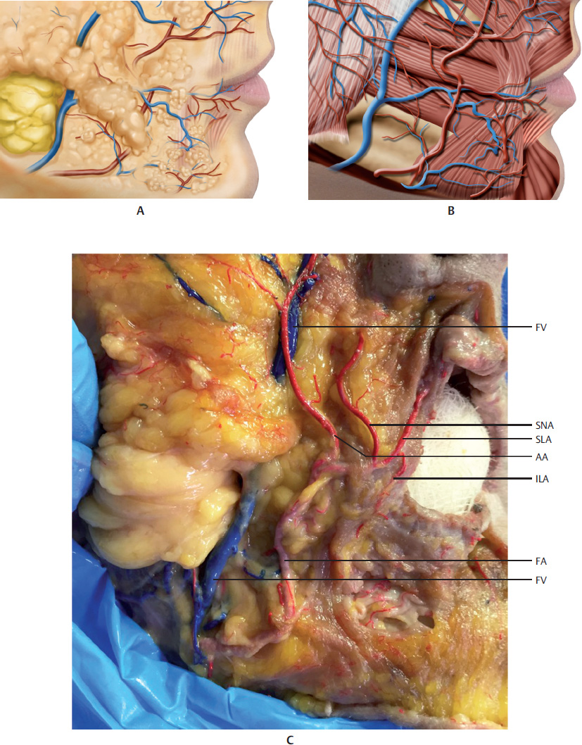
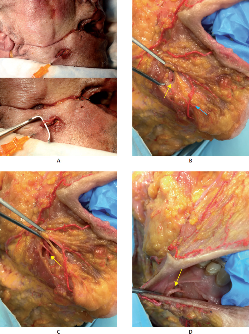
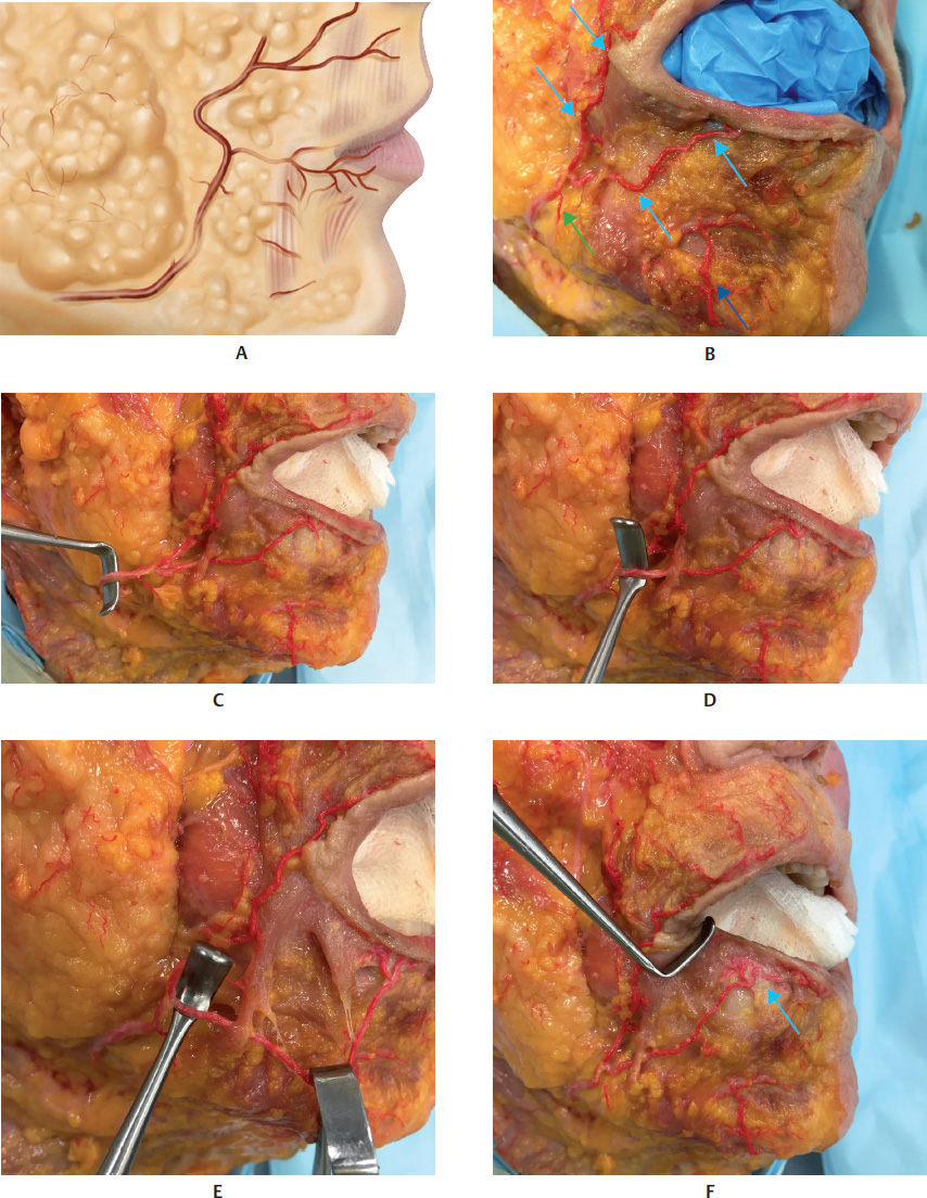
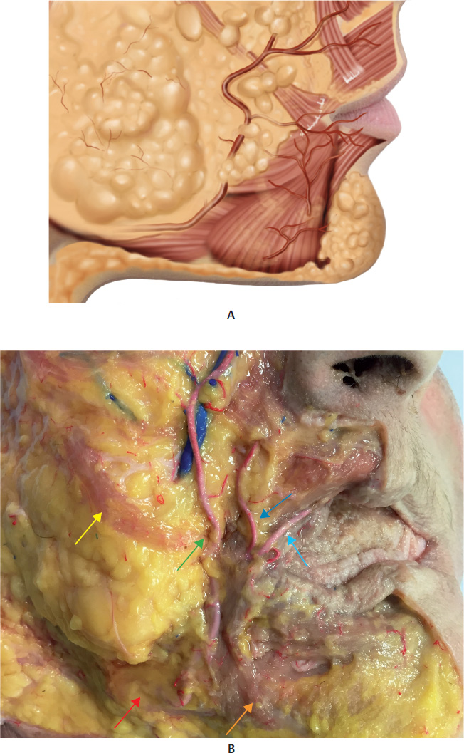
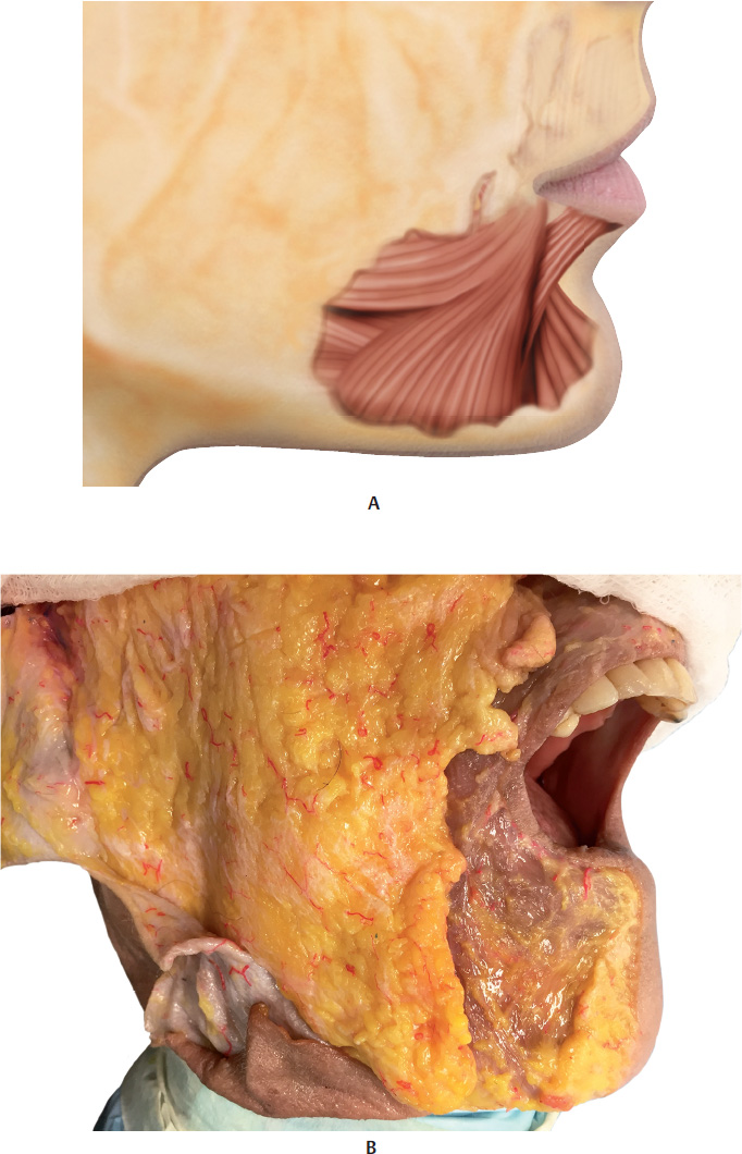
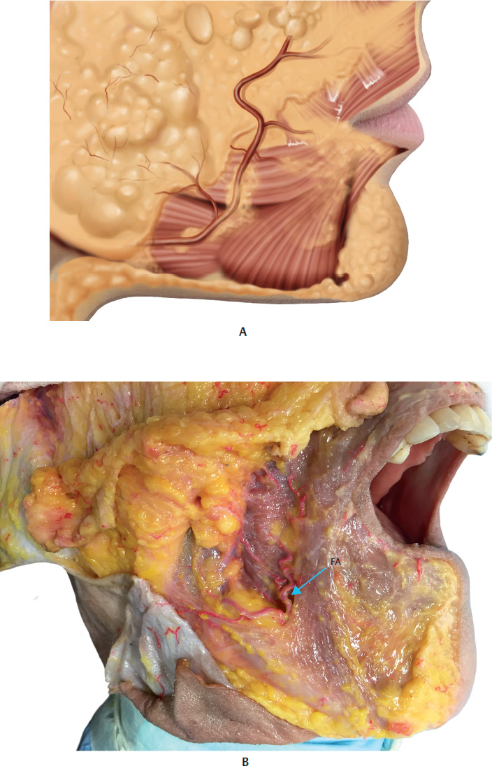
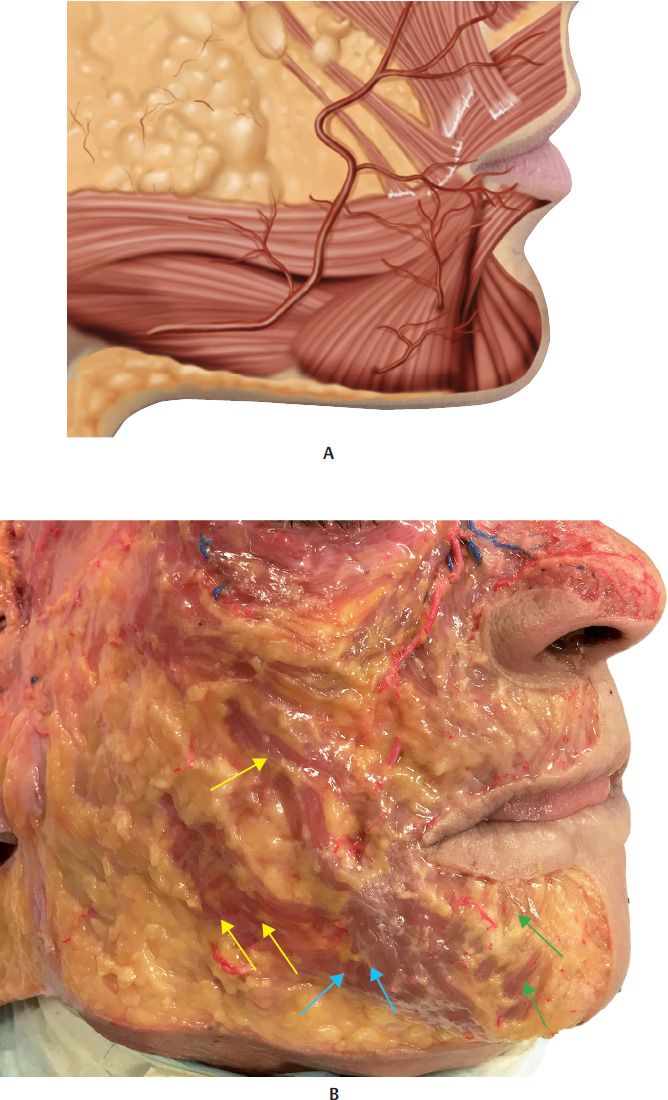
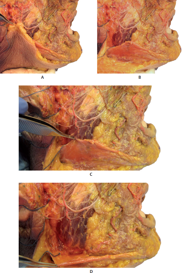
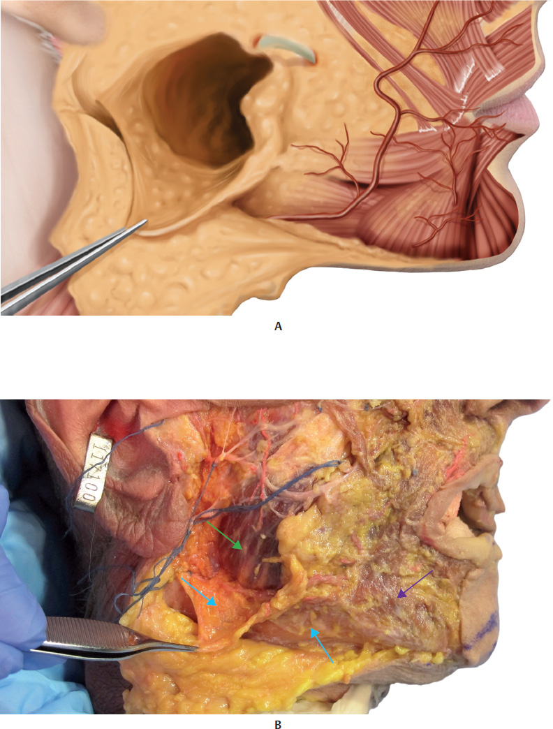
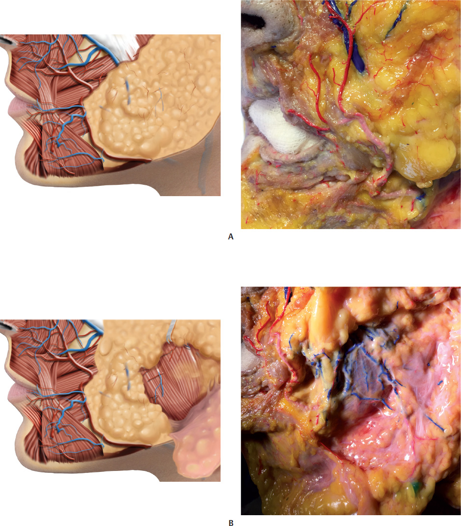
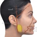
The lower teeth are located on the alveolar part of the man dible. The mental foramen (MF) is in the mandible, below the second premolar tooth; it allows for the passage of the mental nerve and vessels. The facial artery (FA) and facial vein (FV) course around the inferior edge of the mandibular body, and then pass ahead of the anterior edge of the masseter muscle. Their pulses can be easily felt at this point.


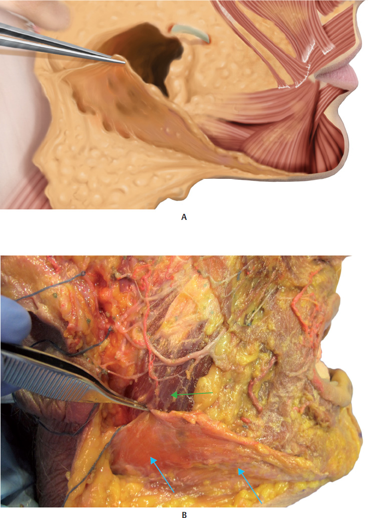
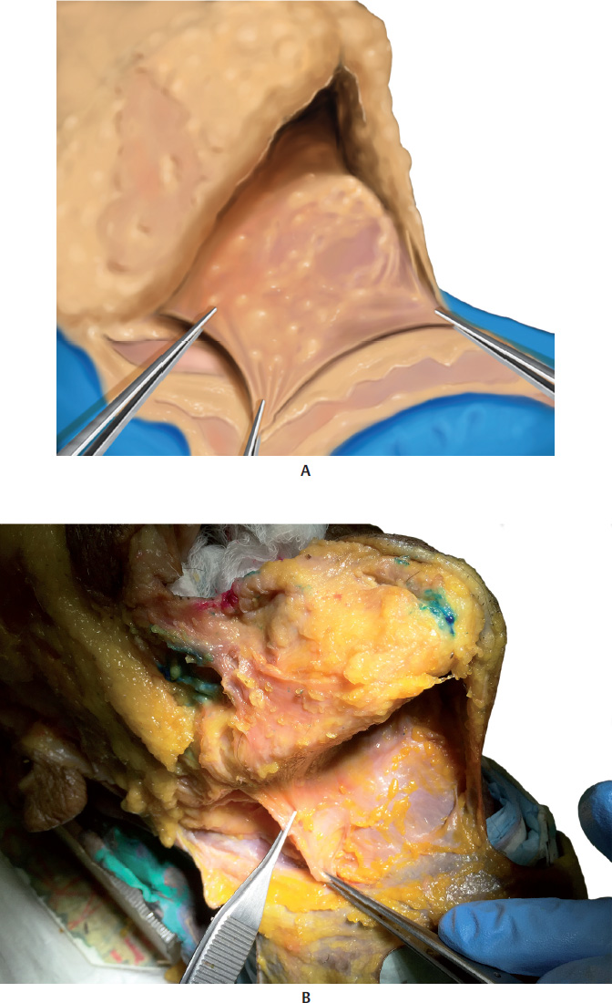
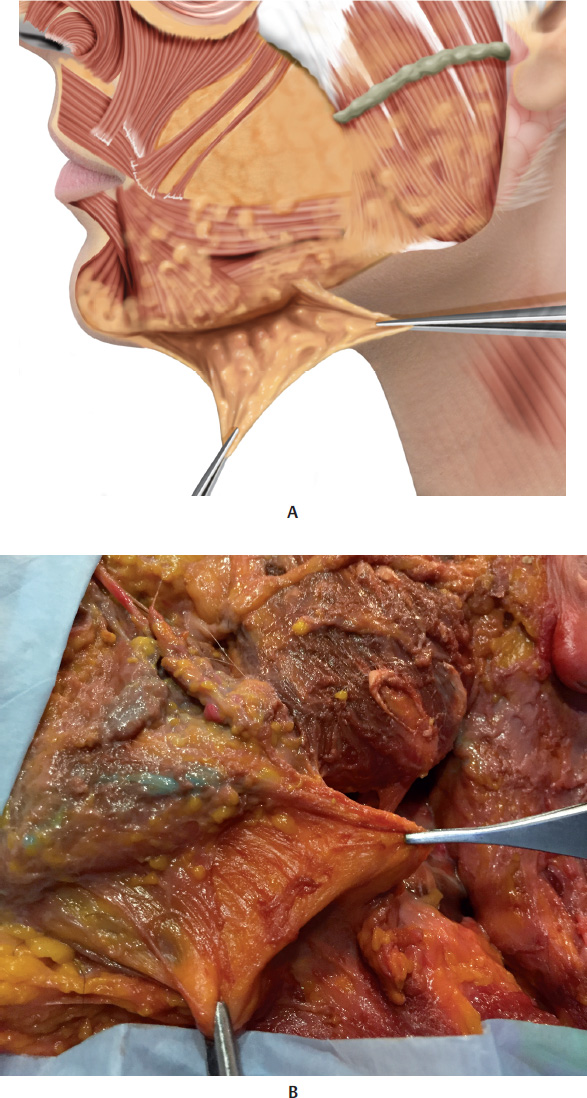
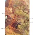
Reece, Pessa and Rohrich identified four clinically relevant fat pads in the mandibular region: two fat pads above the mandibular edge, called the superficial and deep mandibular fat pads, one submandibular fat pad, and another fat pad covering the parotideomasseteric fascia (temporolateral). A membranous septum separates the two fat pads located above the mandibular edge of the submandibular fat pad, and is called the mandibular septum. Anteriorly, this is a continuation of the mandibular ligament, which can then be found behind the depressor muscle of the angle of the mouth (DMAM) before it inserts into the skin. The fibers of the platysma muscle entwine with the mandibular septum and adhere to the anterior edge of the mandible. 6 –. 8


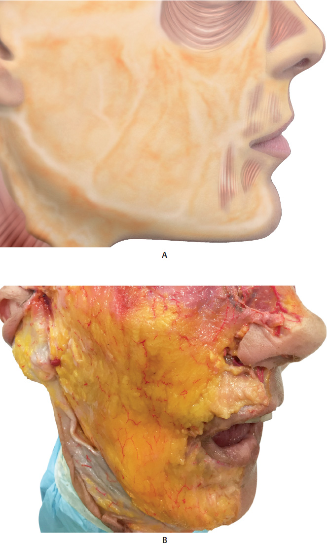
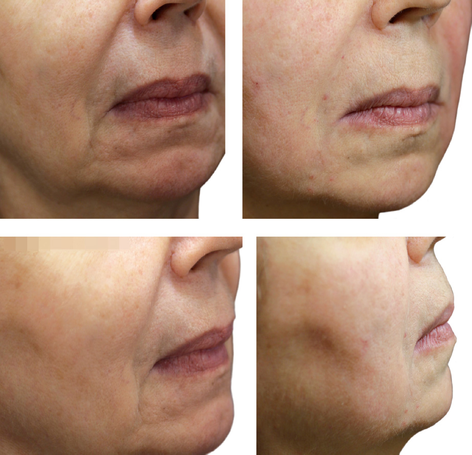
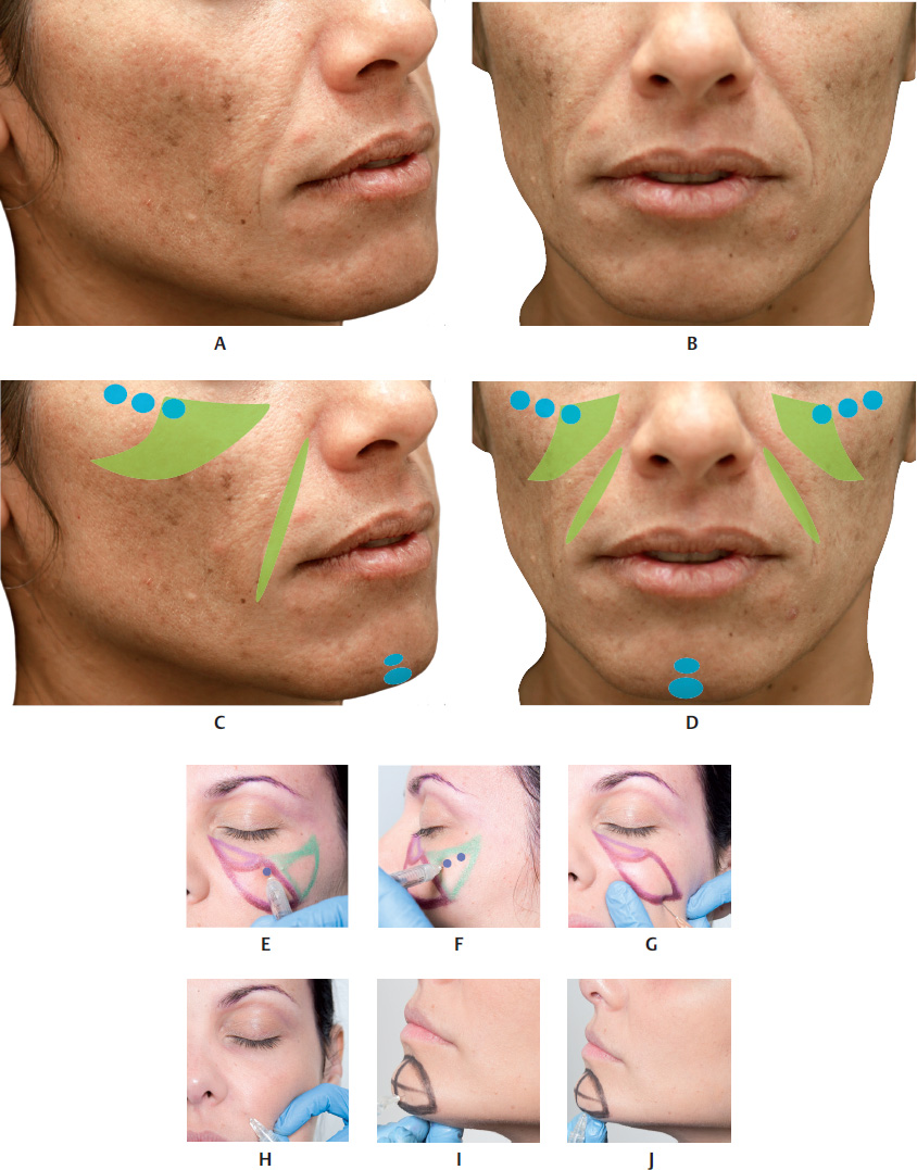
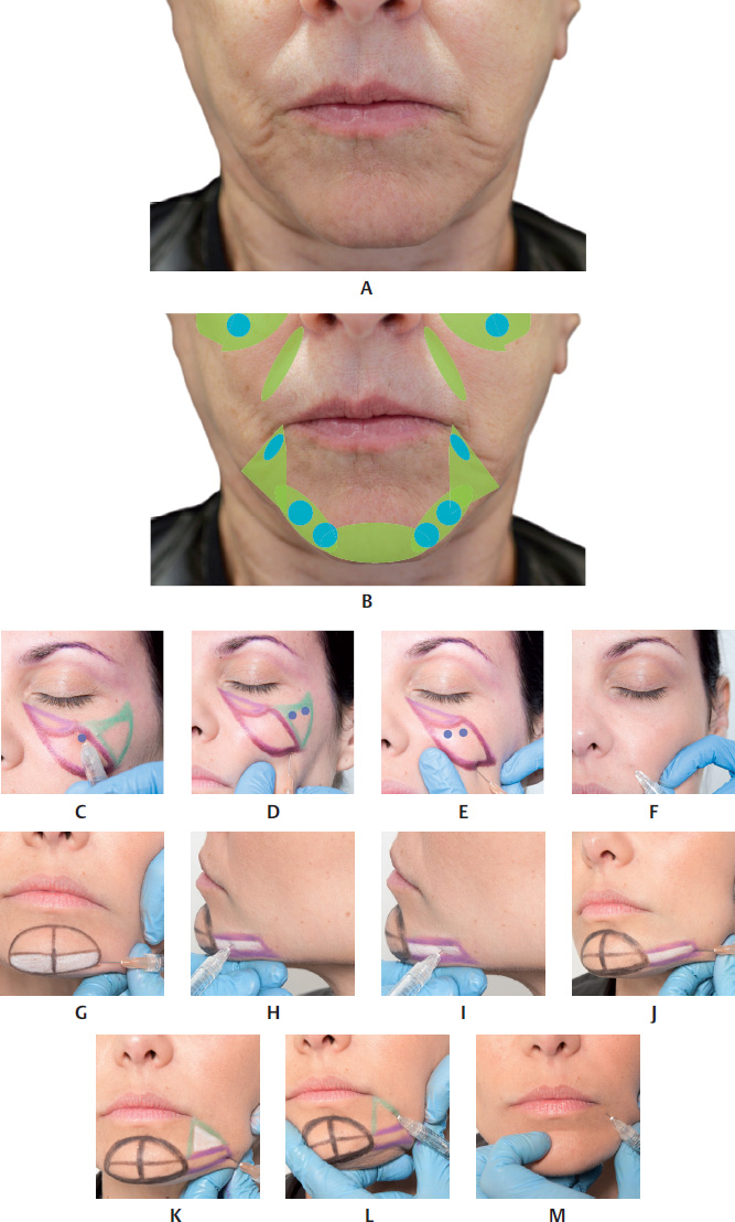
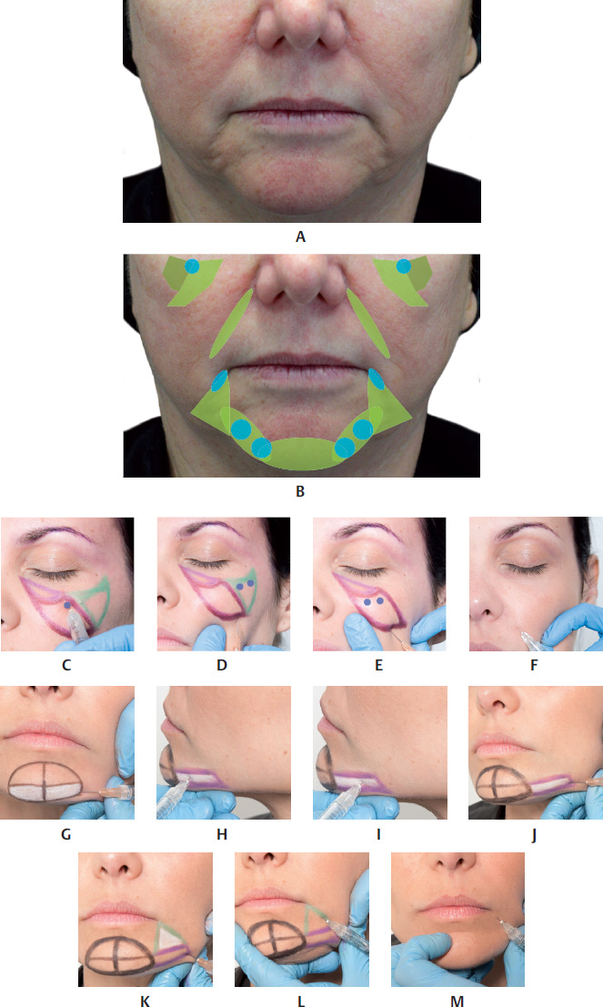
The aging process of the mandibular contour is caused by different mechanisms: atrophy of the superior and inferior mandibular fat pads, with the impression of accentuation in the submandibular fat pad, dehiscence of the mandibular septum with ptosis of the superior and inferior fat pads toward the neck, bone resorption, and flaccidity of local skin (Fig. 17.1–17.20,17.23,17.24, and17.43).


Technique


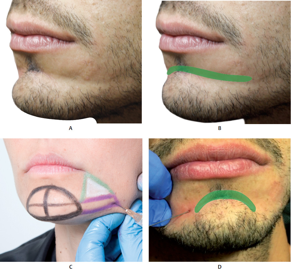
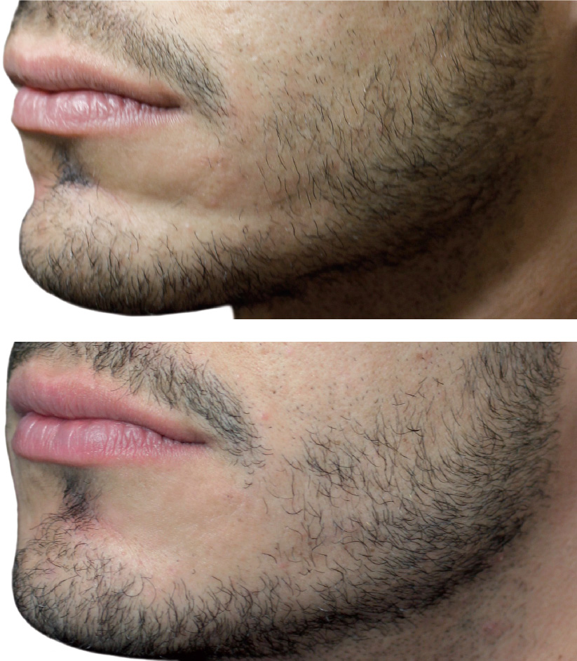
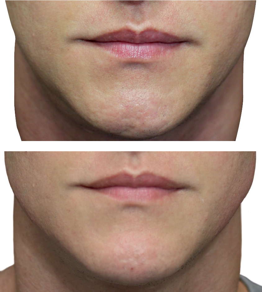
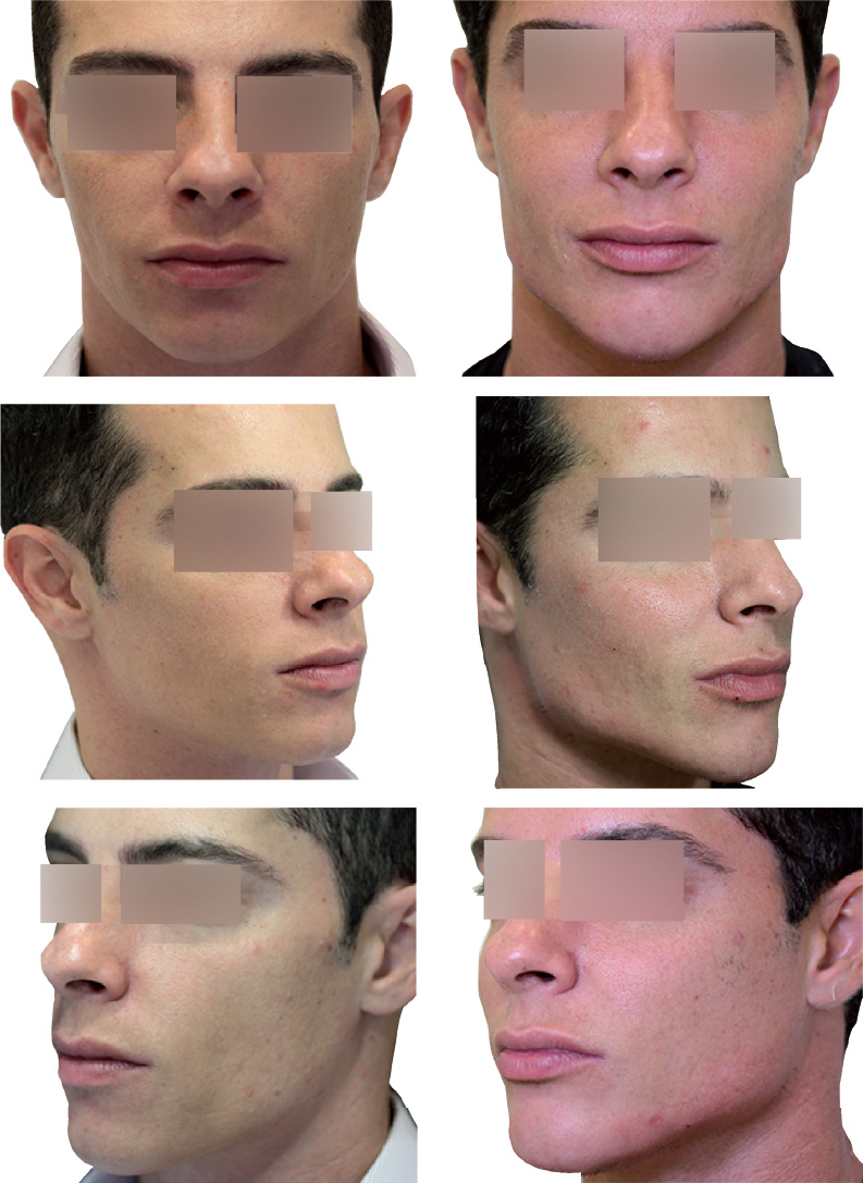
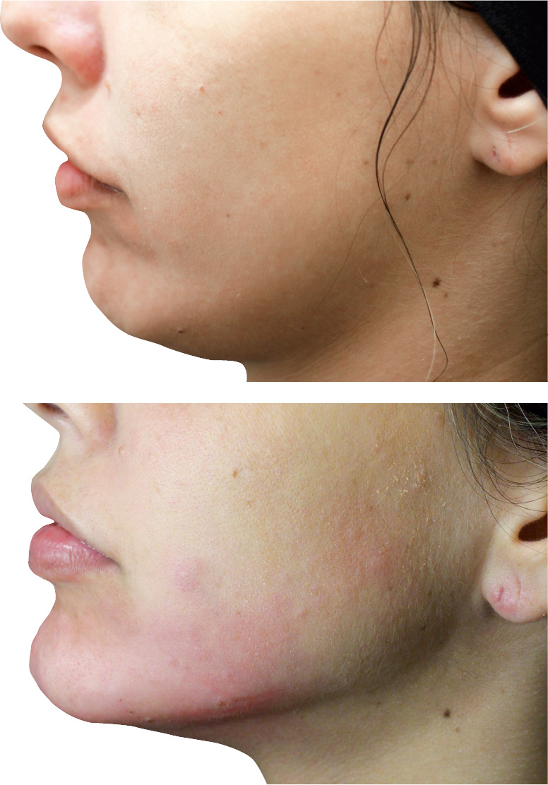
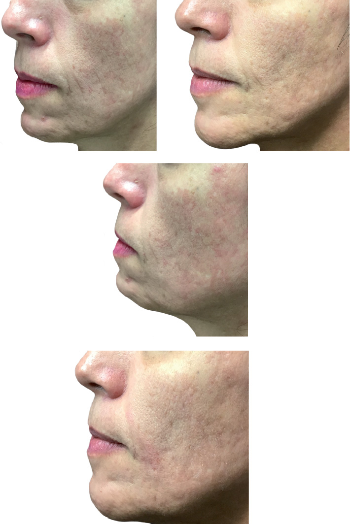
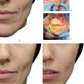
The ideal candidates for this technique include individuals with slight to moderate loss of facial contour. The procedure can also be performed on male patients, to reinforce a region that expresses virility. This augmentation is also indicated for women who have a heart-shaped face, when the wish is to emphasize the lower limit of the face.


For the chin area, the most suitable candidates are those who since youth have needed a chin augmentation (brachyfacials or profile class II) and are reluctant to have definitive implants. Patients who over the years have suffered a change in the format of their chins and require rejuvenation and redefinition of this area are also suitable as candidates.


We prefer to use microcannulas for filling this area. 9 ,. 10 Mi crocannulas have a blunt tip, which offer greater safety as they reduce the risk of injuring vessels and nerves, although the procedure is not completely free of complications: 22 G and 25 G cannulas measuring 40 to 50 millimeters in length are indicated for injecting more viscous HAs, which are considered to bevolumizers.Another important advantage of microcannulas is that the injector can precisely locate the correct injection plane, which is the subdermal plane, and in some cases, the supraperiosteal plane. The blunt tip of the microcannula, which has no cutting capacity, cannot penetrate the dermis, but slides easily in the subdermal plane. Although the areas to be corrected and the respective treatment techniques are described separately, one must not forget that two or three regions can be combined at the same time.


We use three different techniques for treating the mandibular contour depending on the patient’s needs. These are described below.


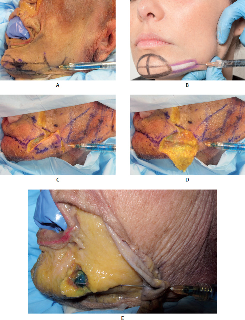
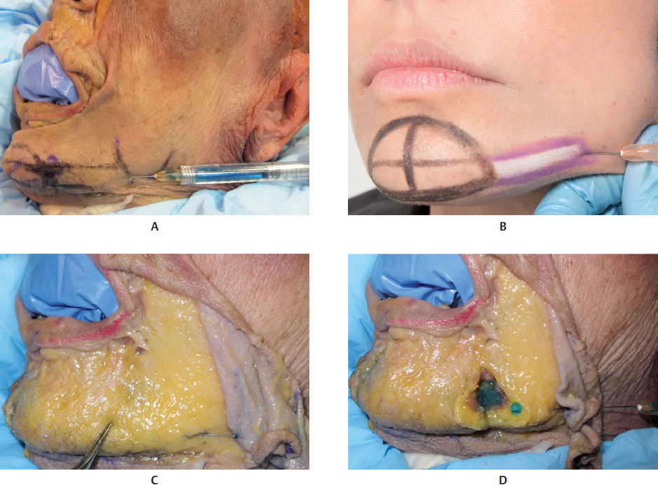
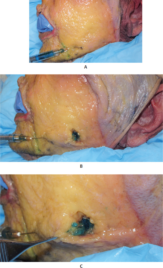
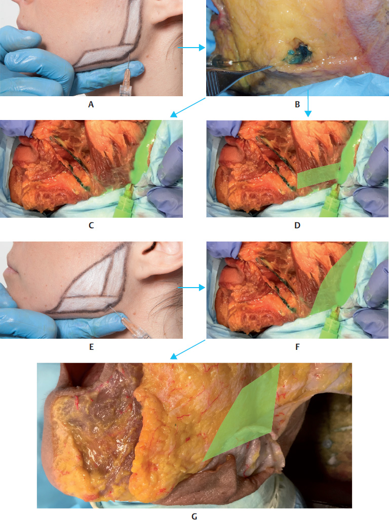
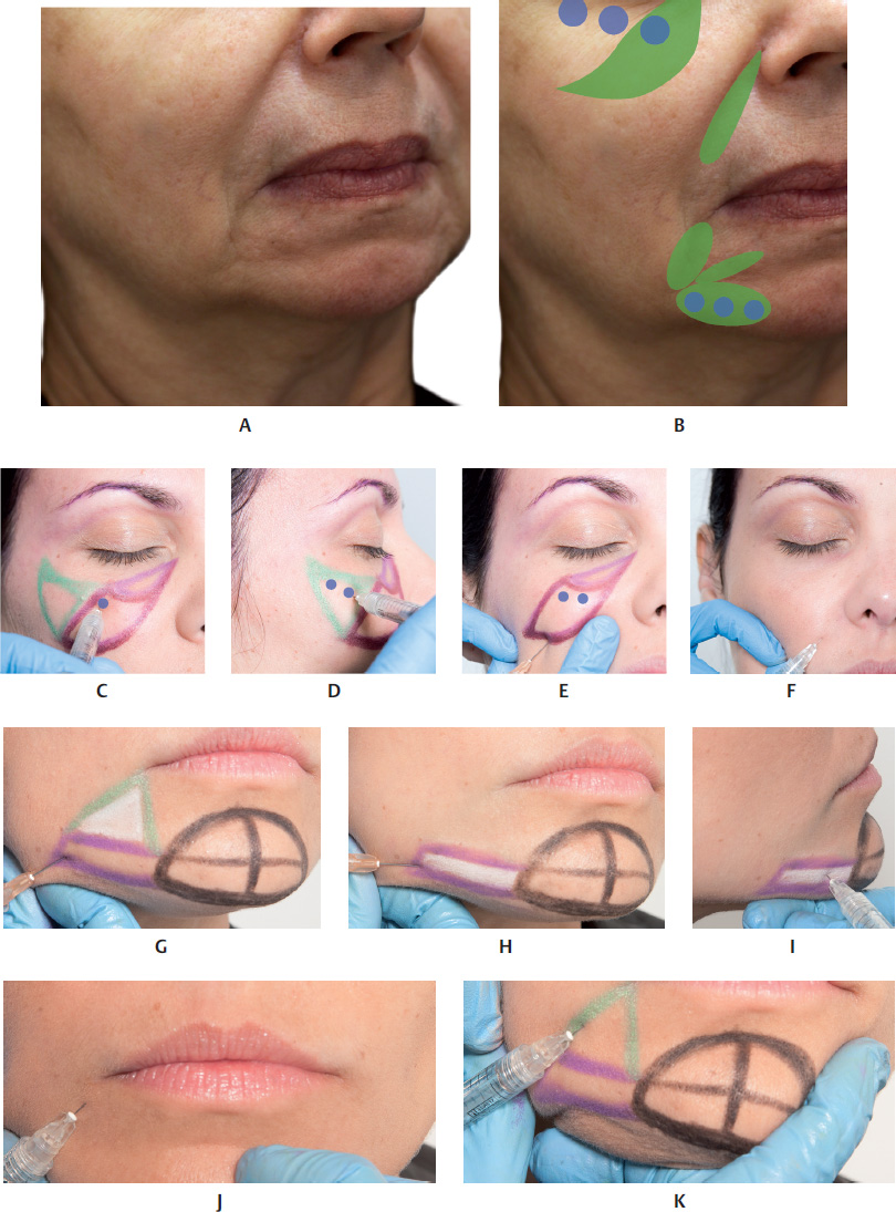
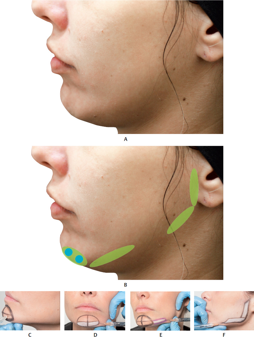
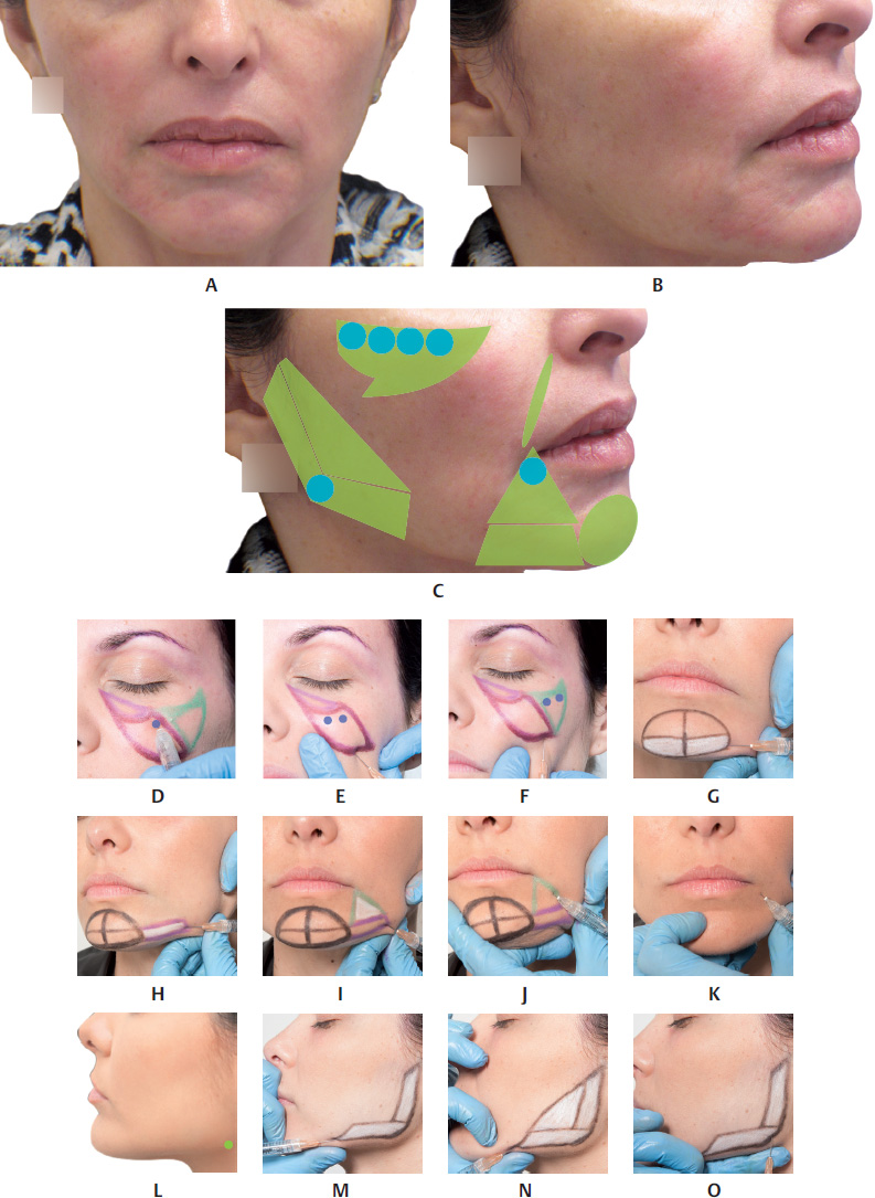
Filler Injection of the Mandibular Angle and Mandibular Ramus


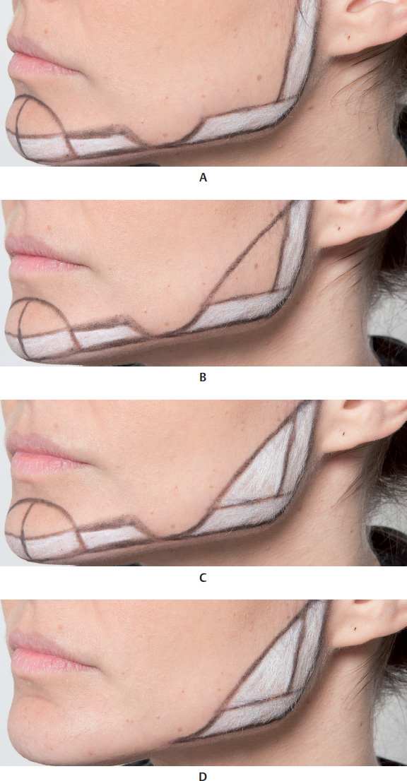
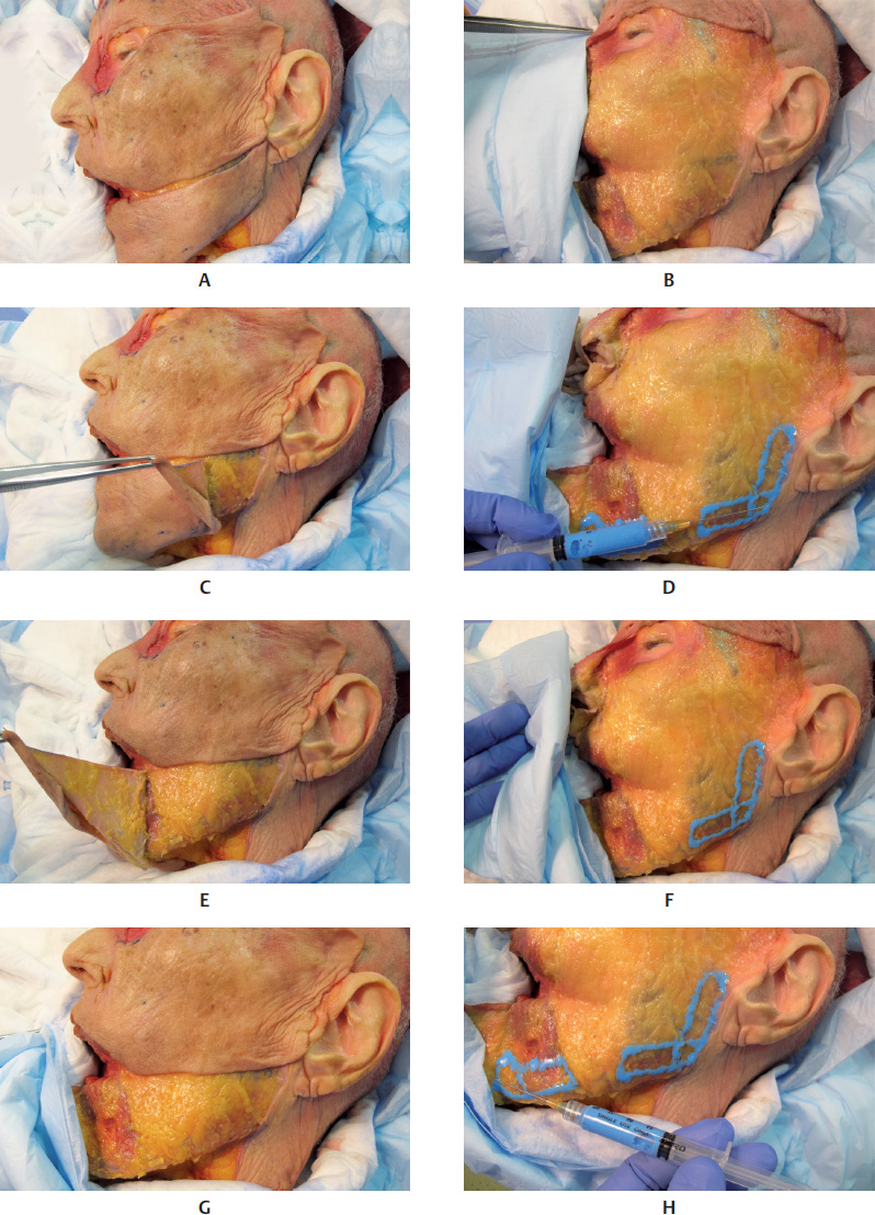
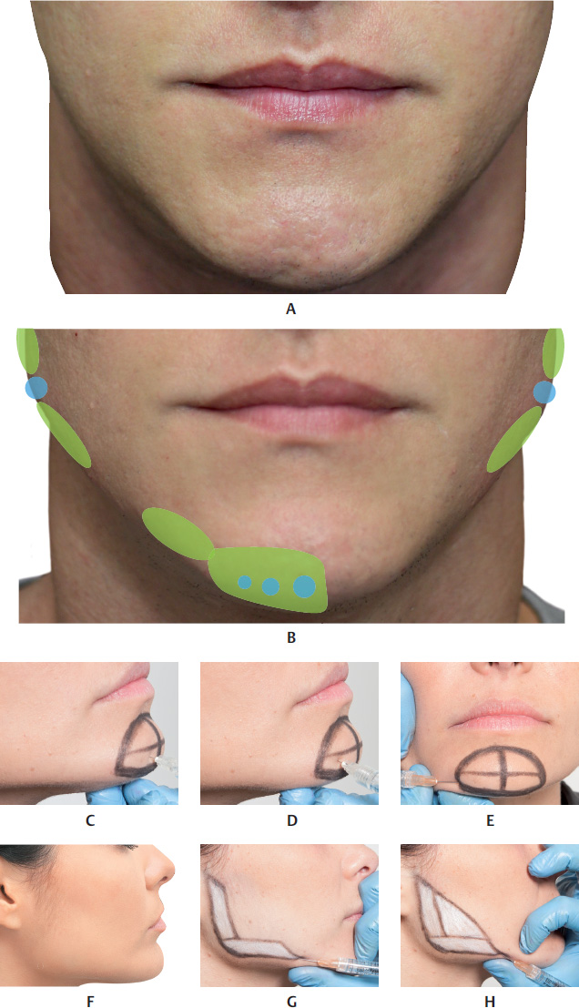
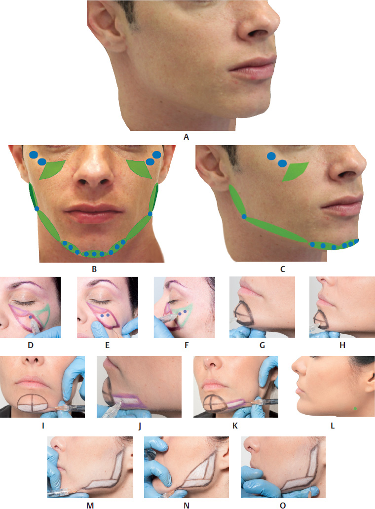
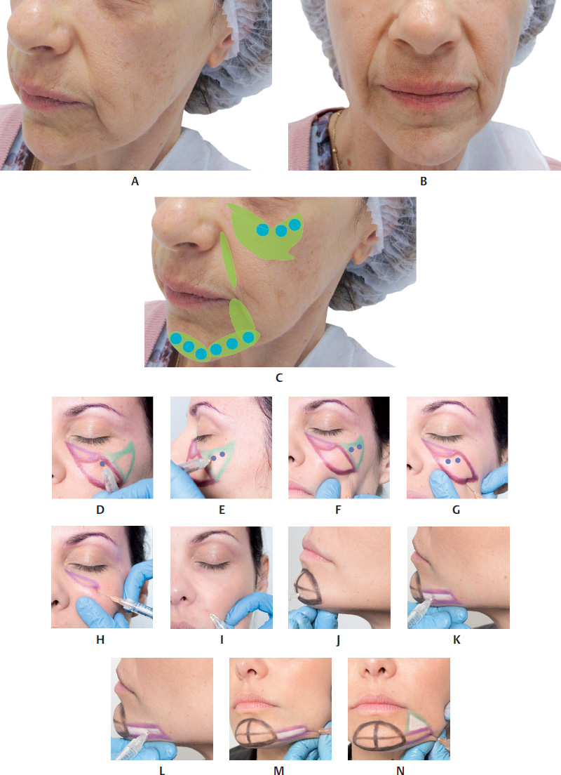
To mark the area, palpate the mandibular angle and draw two lines measuring approximately 3 cm from the mandibular angle: one on the body and one on the ramus. Then, draw a line joining the two extremities, marking the upper limit of the area to be filled.


Create an orifice with a 21 G needle, inserting the bevel very superficially, just enough to pass the fibrotic tissues of the dermis. The entry point can be made in two places: the mandibular angle or at the end of the horizontal line. The injector must pay particular attention because the FA courses along the inferior edge of the body, in front of the anterior margin of the masseter muscle. Insert the microcannula up to the mandibular angle in the subcutaneous plane, where HA should be injected with a retrograde injection. Then, change the direction of the microcannula so that it points toward the mandibular ramus, in the subcutaneous plane, and perform a retrograde injection of the product, filling the previously marked area. After filling, mold the area treated by exerting pressure with the index finger against the mandibular bone (Fig. 17.22,17.39,17.40, and17.42).


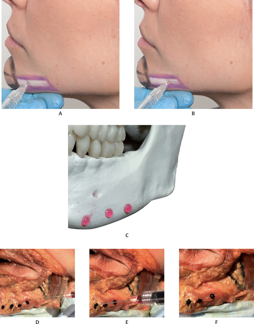
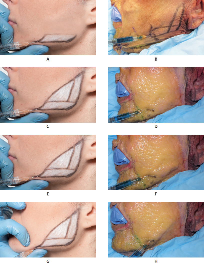
Redefining the Mandibular Line


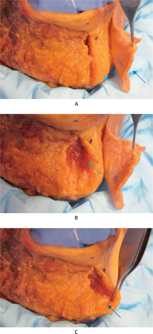
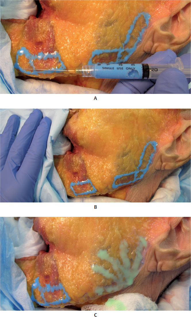
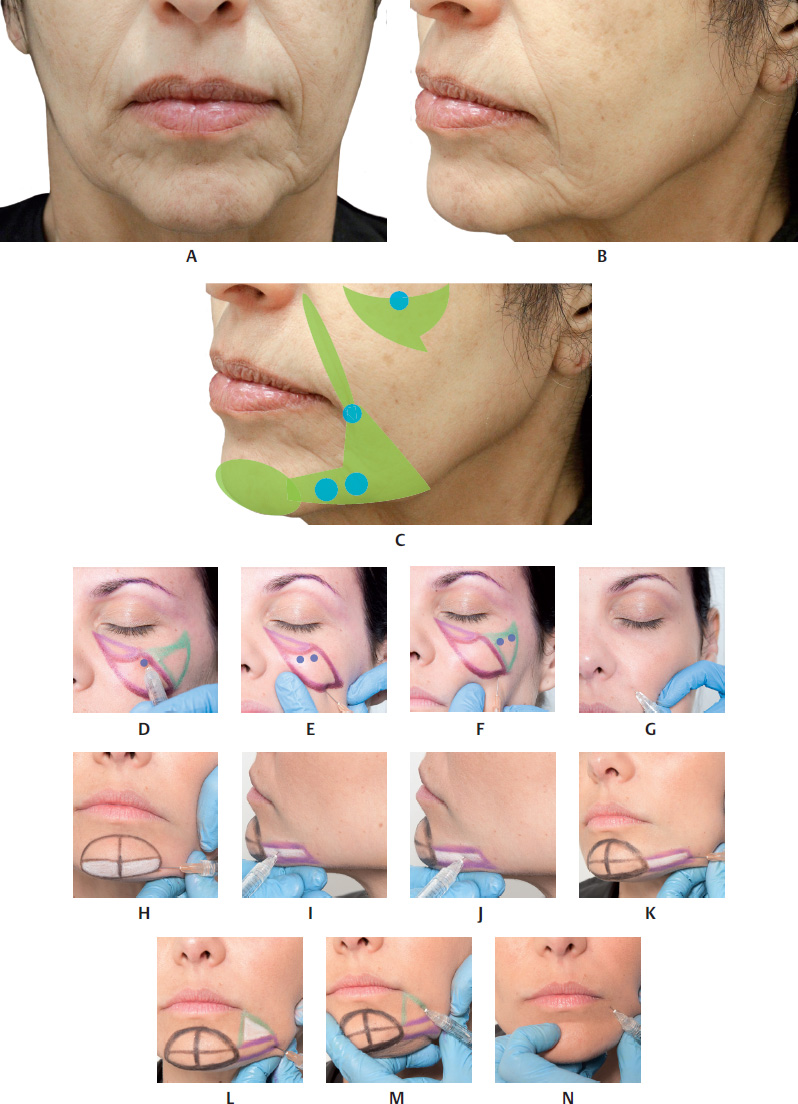
To redefine the mandibular line, mark around the area of ptosis on the mandibular line that is the cause of flaccidity of the skin or movement of the fat pad. After marking the area of ptosis, which should not be filled, draw two parallel horizontal lines marking the mandibular contour up to the mandibular angle. Then, apply an anesthetic bleb (optional) and make an orifice at the site indicated by inserting the abovementioned microcannula in the direction of the mandibular angle, in the subcuta neous plane, and inject the product via retrograde injection. If it is necessary to increase the length of the face, the region below the mandibular septum should also be filled. The filled area should then be molded by exerting moderate pressure (Fig. 17.21,17.22,17.37, and17.38).


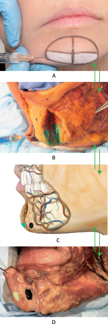
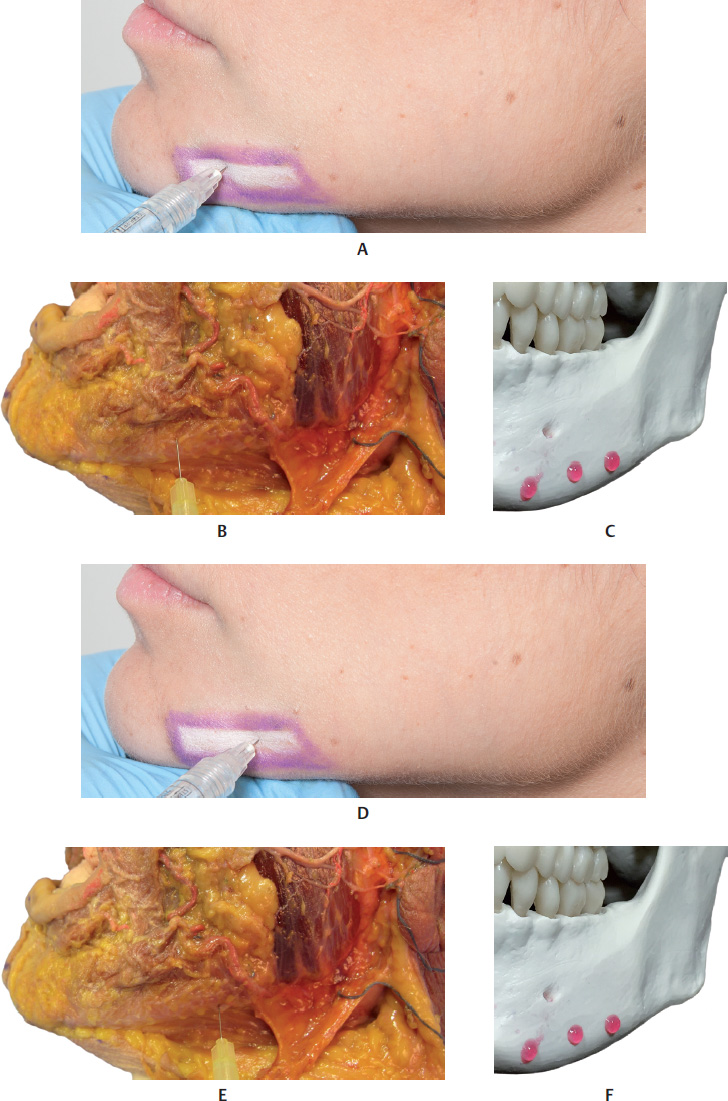
Lateral Mental Region


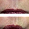
In some people, aging causes lateral volume loss in the mentalis muscle, and this worsens with the loss of dermal collagen with ptosis caused by the subcutaneous fat shifting.


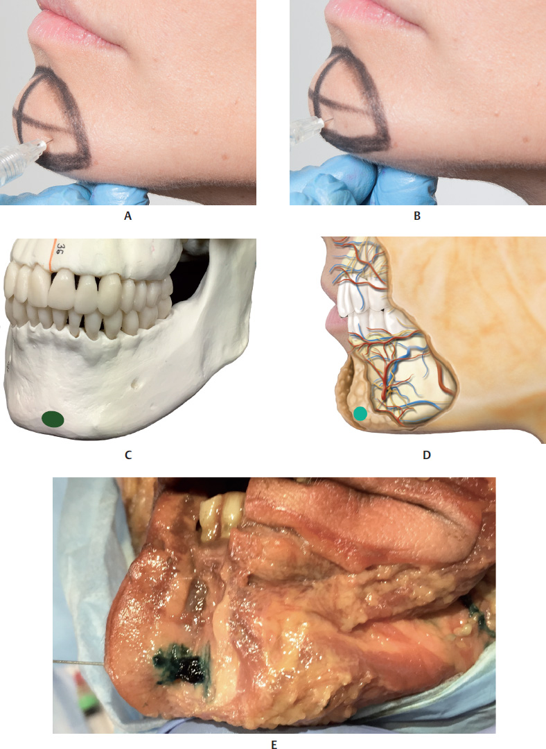
To mark the region to be filled, draw a semicircle on the mental region and another semicircle on the area affected by ptosis on the mandibular line. Draw a line on the mandibular edge joining the two abovementioned markings, and 2 cm above that, draw another parallel line, delimiting the space to be treated.


For filler injections with a microcannula, apply an anesthetic bleb (optional), create an orifice with the needle and then introduce the microcannula between the two parallel lines and f ill the space marked with a retrograde injection technique. Finally, mold the filler by exerting pressure with your index finger against the mandibular bone. This filler injection is applied above the periosteum in the deep subcutaneous plane (Fig. 17.21,17.22,17.31–17.35, and17.41).
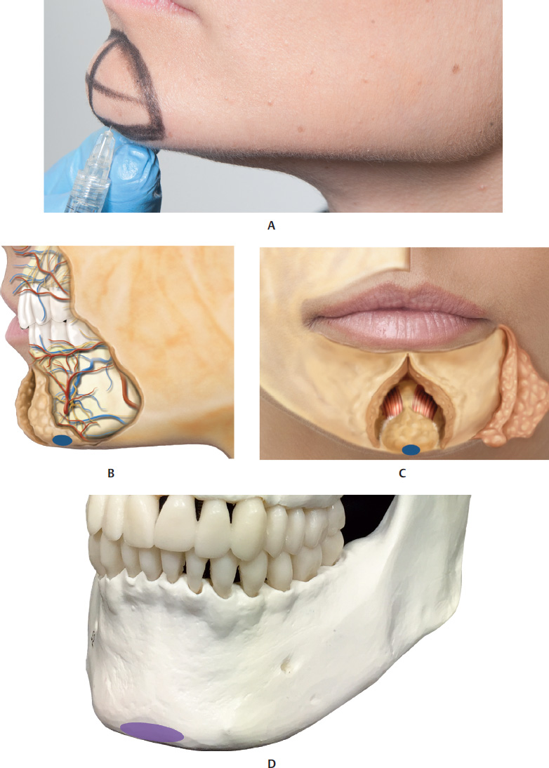
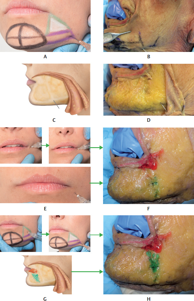
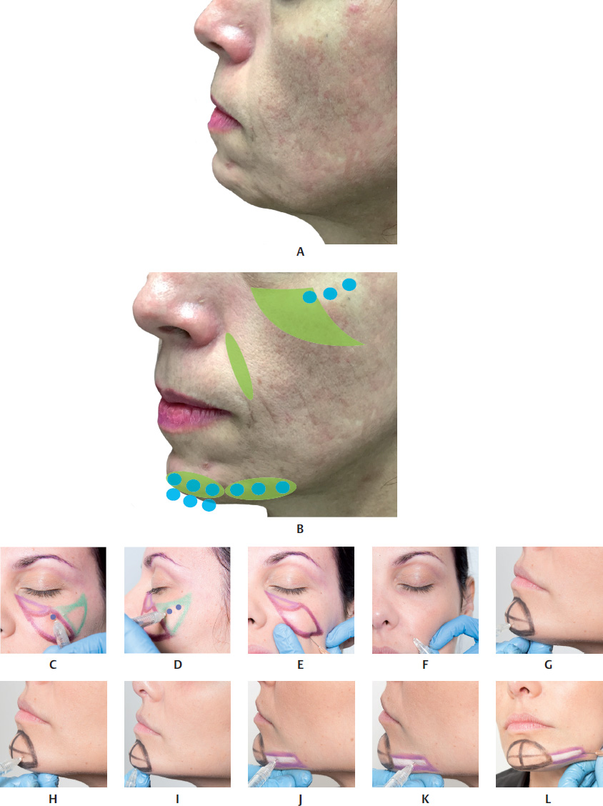
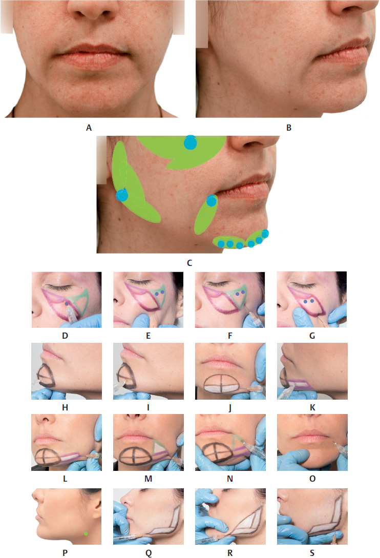


Chin


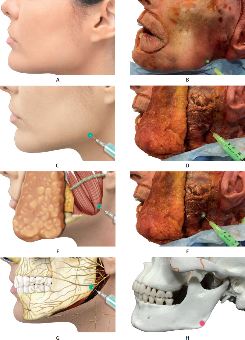
When the patient has a type II facial pattern at the orthodontic evaluation, i.e., a retrognathic chin, orthodontic treatments can be used and orthosurgical correction may be necessary. Filler injections may be indicated to help lessen this structural defect, together with a joint assessment by a dental surgeon. Another indication applies to patients without retrognathia but a disproportionately small chin.


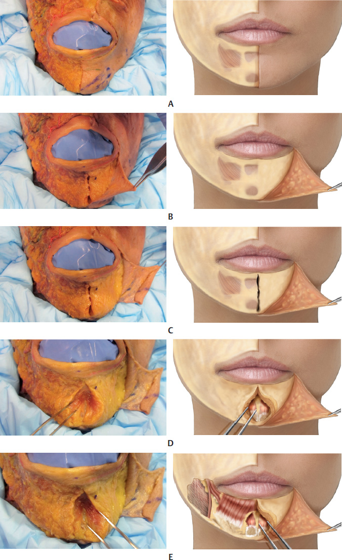
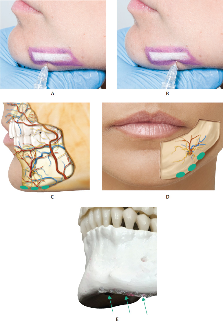
The mental region is composed of three tissue layers: the skin, the muscular-adipose layer, and the central periosteum of the mandible. The muscle layer comprises three muscles: the DMAM, the depressor muscle of the lower lip, and the mentalis muscle, which fuse inferiorly with the platysma. The mentolabial sulcus can be seen in the midline, formed by a fibroelastic lamina that extends from the mandibular symphysis to the skin. Deep in the mentalis muscle, there are two fat pads separated by this sulcus, which do not cross the midline.


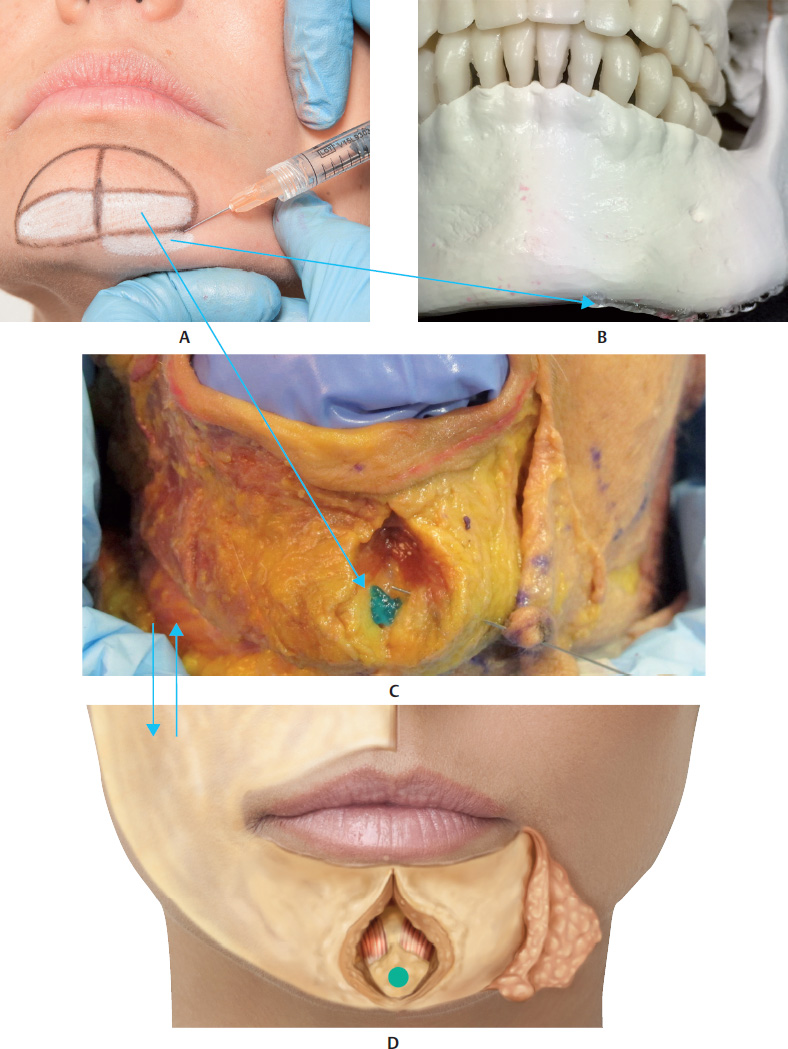
An entry point can be created in up to three different sites for inserting a microcannula or a needle. One option for the orifice is a site located inferiorly to the mental area, inserting the microcannula or needle into the supraperiosteal plane and injecting the product. Another possibility is to insert the needle into the same points marked for the application of botulinum toxin, surpassing the muscle and applying the product to the supraperiosteal plane. For this possibility, we recommend using needles only. Aspire and inject slowly.


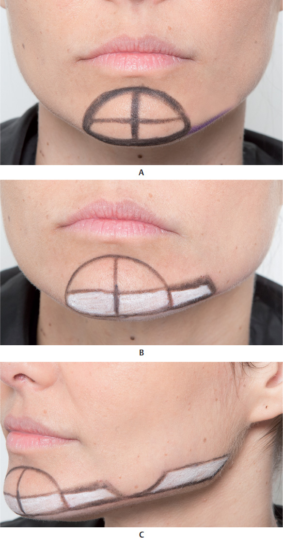
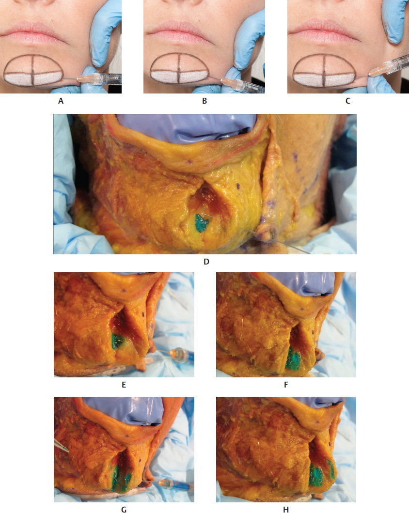
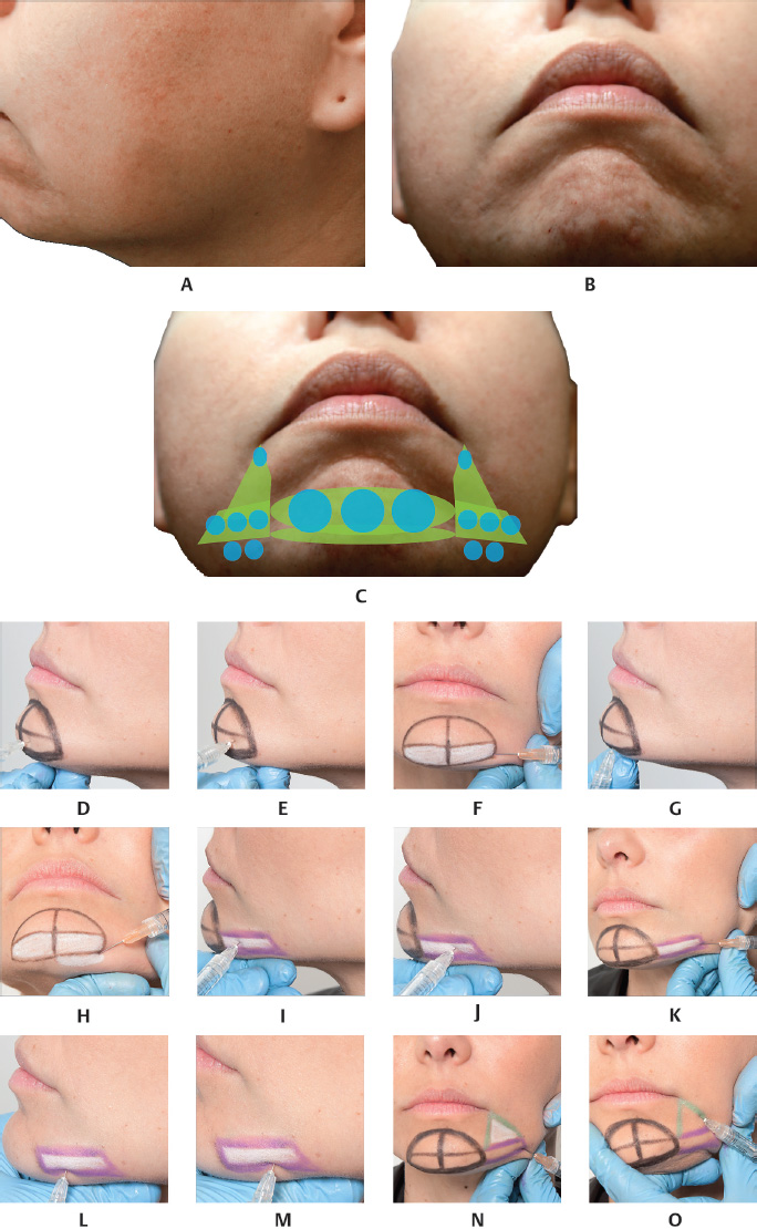
Start by marking the mental area, drawing a line around the chin in the shape of a semicircle up to the mandibular bone bilaterally. Then, draw a vertical line in the middle of the previously marked area, between the two bellies of the mentalis muscle. Palpate the bone base of the area marked and draw a horizontal line up to the semicircle. Then, draw a parallel line 1.5 cm above the previous one. This rectangular figure is the region suggested for the HA filler injection. After asking the patient to contract the chin, we suggest marking two points, one on each belly of the mentalis muscle, for applying 2 to 3 units of botulinum toxin to each point at the same time as the filler injection.


After creating an orifice with the needle, insert the microcannula, reaching the supraperiosteal plane, sliding it to the center of the rectangle on the side that is being treated. At this point, holding the microcannula still, inject between 0.1 and 0.3 ml of the product. In some cases, in order to harmonize the area treated, move the microcannula and inject another 0.1 ml of the product via retrograde injection into the subcutaneous plane above the muscle, in the corresponding rectangular area. Remove the microcannula and mold the region treated using firm and precise movements (Fig. 17.21,17.22,17.25–17.30, and17.41).


Mentolabial Sulcus


See Fig. 17.36.


Clinical Cases


See Figs. 17.44–17.71.


References

1 Carruthers A, Carruthers J, Monheit GD, Davis PG, Tardie G. Multicenter, randomized, parallel-group study of the safety and effectiveness of onabotulinumtoxinA and hyaluronic acid dermal fillers (24-mg/ml smooth, cohesive gel) alone and in combination for lower facial rejuvenation. Dermatol Surg 2010;36(Suppl 4):2121–2134 2 Jefferson Y. Skeletal types: key to unraveling the mystery of facial beauty and its biologic significance. J Gen Orthod 1996;7(2):7–25 3 Reis SAB, Abrão J, Filho LC, Claro CAA. Análise facial subjetiva. Rev Dent Press Ortodon Ortop Facial 2006;11(5):159–172 4 Carruthers JD, Glogau RG, Blitzer A; Facial Aesthetics Consensus Group Faculty. Advances in facial rejuvenation: botulinum toxin type a, hyaluronic acid dermal fillers, and combination therapies—consensus recommendations. Plast Reconstr Surg 2008; 121(5, Suppl):5S–30S, quiz 31S–36S 5 Goss CM. Gray anatomia. 29a edição. Rio de Janeiro: Guanabara Koogan; 1988 6 Reece EM, Pessa JE, Rohrich RJ. The mandibular septum: anatomical observations of the jowls in aging-implications for facial rejuvenation. Plast Reconstr Surg 2008;121(4):1414–1420 7 Reece EM, Rohrich RJ. The aesthetic jaw line: management of the aging jowl. Aesthet Surg J 2008;28(6):668–674 8 Hazani R, Chowdhry S, Mowlavi A, Wilhelmi BJ. Bony anatomic landmarks to avoid injury to the marginal mandibular nerve. Aesthet Surg J 2011;31(3):286–289 9 Braz AV, Mukamal LV, Costa DLM. Manejo cosmético del tercio médio e inferior de la cara. In: Atamoros FP, Merino JE, eds. Dermatologia Cosmética. Cidade do México: Elsevier Masson Doyma; 2011 10 Belmontesi M, Grover R, Verpaele A. Transdermal injection of Restylane SubQ for aesthetic contouring of the cheeks, chin, and mandible. Aesthet Surg J 2006;26(1S):S28–S34
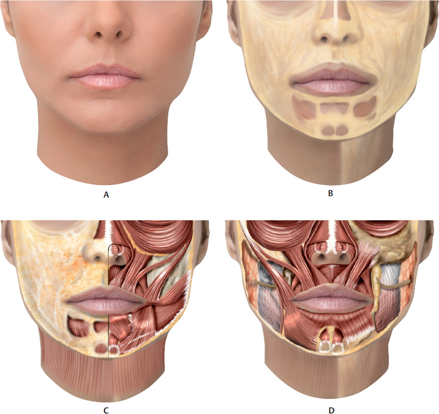
Fig. 17.1 A. Anterior view of the anatomy of the lower third of the face.B. Same region after removal of the skin showing the superficial fat pad (SFP).C. Same region after removal of the skin and SFP in the left side of the face.D. Same region after removal of the skin and SFP. The following muscles are visible: levator muscles of the lip, zygomatic major and minor muscles, risorius muscle, orbicularis oris muscle (OOM), depressor muscle of the angle of the mouth (DMAM), depressor muscle of the lip, mentalis muscle, and platysma muscle.
Fig. 17.2 A. Lower third of the face showing the following muscles: levator muscles of the lips, zygomatic major and minor muscles (of the right side of the face), orbicularis oris muscle (OOM), depressor muscle of the lip, mentalis muscle, and masseter muscle.B. Image similar toA, with removal of the depressor muscle of the lip on the left side of the face.C. Same image with presence, on the left side of the face, of only the following muscles: OOM, depressor muscle of the lip, mentalis muscle, and masseter muscle.D. Bone structure of the maxilla and mandible and part of the buccinator muscle.
Fig. 17.3 A,B. Anterior view of the vascularization of the lower third of the face.
Fig. 1.2 Anterior view of the lower third of the face.A. Corresponding arterial vascularization.B. Corresponding venous vascularization.C. Corresponding innervation.
Fig. 17.5 A. Lateral view of the right side of the face.B. Same region after removal of the skin, showing the superficial fat pads (SFPs).C. Same region after removal of the skin and the SFPs. Note the parotid gland with its respective duct and the following muscles: zygomatic major and minor muscles, risorius muscle, orbicularis oris muscle (OOM), depressor muscle of the angle of the mouth (DMAM), depressor muscle of the lip, mentalis muscle, platysma muscle, and masseter muscle.D. Same image in which the following muscles are visible: OOM, DMAM, depressor muscle of the lip, mentalis muscle, buccinator muscle, and masseter muscle.E. Bone structure of the maxilla and mandible.
Fig. 1.2 Profile view of the right side of the lower third of the face.A. Corresponding vascularization and innervation.B. Corresponding arterial vascularization.C. Corresponding venous vascularization.D. Arterial and venous vascularization integrated in the following muscles: levator muscles of the lip, depressor muscle of the angle of the mouth (DMAM), depressor muscle of the lip, mentalis muscle, buccinator muscle, and masseter muscle.E. Same image after removal of the zygomatic major muscle.F. Same region in which the corresponding innervation is visible.
Fig. 17.7 A andB. Anterior view of the delimitation of the lower third of the face.C andD. Close-ups of imagesA andB.
Fig. 17.8 A. Illustration of right side of the lower third of the face after the skin has been folded back, exposing superficial fat pads (SFPs). The facial vein (FV) and facial artery (FA) and their branches are visible.B. Previous image after the SFPs have been folded back. The FV and FA and their branches are visible.C. The SFPs are being folded back in a fresh cadaver sample. Note that the FV is more lateral and the FA is more medial. The latter branches off proximal to the oral commissure in the inferior labial artery (ILA) and superior labial artery (SLA), and divides into a subnasal artery (SNA) branch that supplies the inferior portion of the ala of the nose. After dividing into these branches, the FA continues its ascending course, and is called the angular artery (AA) in its terminal portion.
Fig. 17.9 A. Lower third of the face of a fresh cadaver specimen in which a window was made in the skin, showing a cannula and the mental artery (MA) being pinched.B. Fresh cadaver after the skin has been folded back, where theyellow arrow indicates the MA that originates in the corresponding foramen and theblue arrow indicates the submental artery.C. Previous image with focus on the MA, indicated by theyellow arrow, below the depressor muscle of the angle of the mouth (DMAM), which is being pinched.D. Oral cavity of a fresh cadaver showing the MA (yellow arrow) exiting the mental foramen (MF).
Fig. 17.10 A. Right side of the lower third of the face after the skin has been folded back, exposing superficial fat pads (SFPs). The facial artery (FA) can be seen branching into the inferior labial artery (ILA) and superior labial artery (SLA).B. Right side of the face of a fresh cadaver specimen showing the FA (green arrow). This branches out into the SLA and ILA indicated by the blue arrows. The darkblue arrow shows the submental artery.C. Close-up of the FA being pinched.D. Close-up of the ILA being pinched.E. Close-up of the facial and inferior labial arteries being pinched and separated by the depressor muscle of the angle of the mouth (DMAM).F. Vermilion border has been folded back and the ILA shown where it enters the deep fat pad of the lips (DFPL) (blue arrow).
Fig. 17.11 A. Right side of the lower third of the face after the skin has been folded back, exposing superficial fat pads (SFPs).B. Right side of the face of a fresh cadaver specimen, showing the SFPs.
Fig. 17.12 A. Right side of the lower third of the face after the skin has been folded back, exposing the deep fat pads (DFPs) below the facial artery (FA) with its branches and the submental artery. The following muscles are visible: orbicularis oris muscle (OOM), zygomatic major muscle, depressor muscle of the angle of the mouth (DMAM), depressor muscle of the lip, and platysma muscle.B. Right side of the face of a fresh cadaver specimen showing the DFPs beneath the following muscles: OOM, zygomatic major muscle (yellow arrow), DMAM (orange arrow), and platysma muscle (red arrow). The following vascular structures are still visible: superior labial artery (SLA) (light blue arrow), subnasal artery (SNA) (dark blue arrow), angular artery (AA) (green arrow), and the blue-colored facial vein (FV).
Figure 17.13 A. Right side of the lower third of the face after the skin has been folded back, exposing superficial fat pads (SFPs). The SFPs folded back more medially to show the following muscles: risorius muscle, depressor muscle of the angle of the mouth (DMAM), depressor muscle of the lip, mentalis muscle, and platysma muscle.B. Right side of the face of a fresh cadaver specimen showing exactly what was described inA.
Fig. 17.14 A. Right side of the lower third of the face after the skin has been folded back, exposing the deep fat pads (DFPs) below the facial artery (FA) with its branches. The following muscles are visible: orbicularis oris muscle (OOM), risorius, depressor muscle of the angle of the mouth (DMAM), depressor muscle of the lip, and platysma muscle.B. Right side of the face of a fresh cadaver specimen showing exactly what was described inA, with focus on the FA (blue arrow).
Fig. 17.15 A. Right side of the lower third of the face after the skin has been folded back, exposing the deep fat pads (DFPs) below the facial artery (FA) with its branches. The following muscles are visible: orbicularis oris muscle (OOM), zygomatic major muscle, risorius muscle, depressor muscle of the angle of the mouth (DMAM), depressor muscle of the lip, mentalis muscle, and platysma muscle.B. Right side of the face of a fresh cadaver specimen showing what was described inA, with focus on the following muscles: zygomatic major muscle (top yellow arrow), platysma muscle (bottom yellow arrows), DMAM (blue arrows), and depressor muscle of the lip (green arrows).
Fig. 17.16 A. Right profile view of the lower third of the face of a fresh cadaver with skin pinched above part of the platysma muscle.B. Previous image with the skin folded back in which the platysma muscle can be seen covering part of the masseter muscle.C. Previous image with the platysma muscle being pinched and covering part of the masseter muscle.D. Previous image with the platysma muscle being pinched and folded back to reveal the masseter muscle and the parotid gland behind it.
Fig. 17.17 A. Right profile view of the lower third of the face with the platysma muscle being pinched and folded back, revealing the masseter muscle.B. Right profile view of the lower third of the face of a fresh cadaver with the platysma muscle being pinched and folded back (blue arrows). The masseter muscle is visible beneath the platysma muscle (green arrow). The depressor muscle of the angle of the mouth (DMAM) (purple arrow) is visible medially.
Fig. 17.18 A. Right profile view of the lower third of the face with the platysma muscle being pinched, revealing the following muscles: zygomatic major muscle, risorius muscle, depressor muscle of the angle of the mouth (DMAM), depressor muscle of the lip, and mentalis muscle.B. Right profile view of the lower third of the face a fresh cadaver with the platysma muscle being pinched (blue arrows) above the masseter muscle (green arrow).
Fig. 17.19 A. Lower third of the face and cervical region with the platysma muscle being pinched.B. Right profile view of the lower third of the face and cervical region of a fresh cadaver with the platysma muscle being pinched. Note the extension of the platysma muscle wrapped around the mandibular bone up to the portion corresponding to the cervical region.
Fig. 17.20 A. Lower third of the face and cervical region with the platysma muscle being pinched. Note the integration of the platysma muscle in its cervical and mandibular portions. The following muscles are still visible: risorius muscle, depressor muscle of the angle of the mouth (DMAM), depressor muscle of the lip, mentalis muscle, and, more laterally, the masseter muscle.B. Right profile view of the lower third of the face and cervical region of a fresh cadaver with the platysma muscle being pinched, where the integration of the platysma muscle is visible in its cervical and mandibular portions.
Fig. 17.21 A. Markings for filler injection to the chin described under Techniques.B. Markings for filler injection in the lateral mental region described under Techniques. The areas to be filled in the chin and the lateral mental region have been marked inwhite.C. Markings for filler injection in the mandibular line described under Techniques. The areas to be filled in the chin, lateral mental region, and mandibular line have been marked inwhite. Note that the area corresponding to the jowl fat has not been filled.
Fig. 17.22 A, B, andC. Markings described under Techniques for filler injection in the chin, lateral mental region, mandibular line, ramus of the mandible, and mandibular angle.D. Markings described under Techniques, only for filler injections in the mandibular line, ramus of the mandible, and mandibular angle.
Fig. 17.23 A. Lower third of the face of a cadaver and corresponding illustration, showing the mental superficial fat pad (SFPM) on the right side of the face, and the skin on the left side of the face.B andC. Same image in which the skin is being folded back from the left side of the face, showing the superficial fat pad (SFP) of the chin.D. Same image with the right portion of the mentalis muscle being pinched, located behind the SFPM.E. Same image with the left portion of the mentalis muscle being pinched, located behind the SFPM. The depressor muscle of the lip is visible over the mentalis muscle in the illustration.
Fig. 17.24 A. Lower third of the face of a fresh cadaver showing the skin being folded back from the left side of the face (dark blue arrow) and revealing the mental superficial fat pad (SFPM) (light blue arrow).B. Same image in which the skin and the SFPM have been folded back to reveal the left portion of the mentalis muscle (green arrow).C. Same image in which the skin, SFPM, and mentalis muscle have been folded back to reveal the mental deep fat pad (MDFP) (blue arrow). This supraperiosteal plane is the best for filler injections in the chin.
Fig. 17.25 A, B, andC. Cannula inserted in different directions and application planes in the chin of a model.D. Lower third of the face of a fresh cadaver showing a cannula inserted into the mental deep fat pad (MDFP) behind the mentalis muscle. Thegreen-colored hyaluronic acid (HA) is visible at the site.E andF. Same image in profile revealing thegreen-colored HA being injected into the mental deep fat pad (MDFP).G andH. Same image in profile, revealing thegreen-colored HA being injected into the mental deep and mental superficial fat pads (MDFP and SFPM), below and above the mentalis muscle, respectively.
Fig. 17.26 A. Cannula inserted into the submuscular plane of a model in a submental direction for a filler injection in the same area.B. Lower third of a cranium showing hyaluronic acid (HA) in the supraperiosteal submental area.C. Lower third ofthe face of a fresh cadaver showing a cannula inserted between the periosteum and the mental deep fat pad (MDFP) behind the mentalis muscle. Thegreen-colored HA is visible at the site.D. Illustration corresponding toC.
Fig. 17.27 A. andB. Needle inserted in two different positions in the supraperiosteal plane in the chin of a model.C. Lower third of a cranium showing a supraperiosteal application point for the filler in the mental area.D. Illustration in profile of the lower third of the cranium, showing the supraperiosteal application point for the filler in the previous figure. Note that even with the needle injecting into the periosteum, the product penetrates the MDFP and remains there.E. Profile view of the lower third of the face of a fresh cadaver showinggreen-colored HA, which was injected with a needle into the supraperiosteal plane of the chin. Note that even with the needle injecting into the periosteum, the product penetrates the MDFP and remains there.
Fig. 17.28 A. Needle inserted into the supraperiosteal plane in the submental area of a model.B. Illustration in profile of the lower third of the cranium, showing the supraperiosteal application point for the filler in the submental region. Note that even with the needle injecting into the periosteum, the product penetrates the MDFP and remains there.C. Illustration similar toB, but seen from the front.D. Lower third of a cranium showing a supraperiosteal application point for the filler in the submental area.
Fig. 17.29 A. Needle inserted into the supraperiosteal plane in the chin of a model.B. Lower third of a cranium showing a supraperiosteal application point for the filler in the mental area.C. Illustration in profile of the lower third of the cranium showing the supraperiosteal application point for the filler in imageB. Note that even with the needle injecting into the periosteum, the product penetrates the MDFP and remains there.D. Profile view of the lower third of the face of a fresh cadaver showinggreen-colored hyaluronic acid (HA), which was injected with a needle into the supraperiosteal plane of the chin. Note that even with the needle injecting into the periosteum, the product penetrates the MDFP and remains there.
Fig. 17.30 A. Cannula inserted into the submuscular plane of the chin of a model for a filler injection in the same area.B. Lower third of the face of a fresh cadaver showing a cannula inserted into the mental superficial fat pad (SFPM) in front of the mentalis muscle. Thegreen-colored hyaluronic acid (HA) is visible in two application planes, SFPM, MDFP, and the chin.C. Illustration in profile demonstrating pointB. Note theblack circle symbolizing the injection with cannula into the supraperiosteal plane with the product penetrating the MDFP, where it remains, and thegreen circle symbolizing an injection with cannula in the more superficial plane of the SFPM above the mentalis muscle.D. Profile view of the lower third of the face of a fresh cadaver showing ablack dot, symbolizing an injection with cannula in the supraperiosteal plane with the product penetrating the MDFP, where it remains. There is also agreen dot, where the HA was injected with a cannula into the more superficial plane of the SFPM above the mentalis muscle.
Fig. 17.31 A. Profile view of the lower third of the face of a fresh cadaver with cannula inserted into the lateral mental region for a filler injection.B. Profile view of the lower third of the face of a model with cannula inserted into the lateral mental region for a filler injection.C andD. Profile view of the lower third of the face of a fresh cadaver with cannula inserted into the lateral mental region. The skin and the superficial fat pad (SFP) of this region have been folded back and the cannula can be seen in the submuscular plane below the depressor muscle of the angle of the mouth (DMAM).E. Lower third of the face of a fresh cadaver with the skin folded back and cannula inserted into the submuscular plane below the DMAM, wheregreen-colored hyaluronic acid (HA) can be seen.
Fig. 17.32 A. Profile view of the lower third of the face of a fresh cadaver with cannula inserted into the lateral mental region for a filler injection.B. Profile view of the lower third of the face of a model with cannula inserted into the lateral mental region for a filler injection.C. Lower third of the face of a fresh cadaver with the skin folded back and cannula inserted into the supramuscular plane in the lateral mental superficial fat pad (SFPM).D. Lower third of the face of a fresh cadaver, with cannula inserted into the supramuscular plane, above the depressor muscle of the angle of the mouth (DMAM) in the superficial fat pad (SFP) in this area. The hyaluronic acid (HA) injected previously can also be seen in the submuscular plane. Thegreen-colored HA is visible in both planes mentioned.
Fig. 17.33 A. andB. Profile view of the lower third of the face of a model with needle inserted in different positions in the supraperiosteal plane of the lateral mental region for filler injection.C. Lower third of a cranium showing three suggestions for supraperiosteal application points in the lateral mental region.D, E, andF. Profile view of the lower third of the face of a fresh cadaver with needle inserted in different positions in the supraperiosteal plane of the lateral mental region.
Fig. 17.34 A. Profile view of the lower third of the face of a model with needle inserted in different positions in the supraperiosteal plane of the lateral mental region for filler injection.B. Profile view of the lower third of the face of a fresh cadaver with needle inserted into the lateral mental region in the supraperiosteal plane. The needle can be seen through the DMAM.C. Lower third of a cranium showing three suggestions for supraperiosteal application points in the lateral mental region.D. Same image as inA with needle inserted in a more lateral position.E. Same image as inB with needle inserted in a more lateral position.F. Image similar toC.
Fig. 17.35 A. andB. Profile view of the lower third of the face of a model with needle inserted in different positions in the inferolateral mental region in the supraperiosteal plane for filler injection.C andD. Illustration and lower third of the face of a model with overlays of the cranium showing three suggested points for applying filler injections in the supraperiosteal plane in the inferolateral mental region. The mental foramen (MF) and corresponding structures are visible.E. Lower third of a cranium showing a simulation of supraperiosteal filler injection with hyaluronic acid (HA) in the inferolateral mental region.
Fig. 17.36 A andB. Profile view of the lower third of the face of a model and of a fresh cadaver with cannulas inserted into the mentolabial region (marionette line).C andD. Illustration corresponding to a fresh cadaver with cannula inserted into the mentolabial region (marionette line).E. Anterior images of a model with needle inserted into the intradermal/subcutaneous plane of the oral commissure.F. Image of a fresh cadaver with hyaluronic acid (HA) coloredin red, simulating a filler injection in the oral commissure suggested inE.G. Profile views of a model with needle and cannula used to fill the oral commissure and the mentolabial region (marionette line), respectively. Below, see the illustration simulating the result of the treatment suggested above.H. Image of a fresh cadaver withred– andgreen-colored HAs, simulating filler injections in the oral commissure and in the mentolabial region (marionette line), respectively, suggested inG.
Fig. 17.37 A. Markings for filler injection with cannula in the mandibular line, where the area to be filled has been marked inwhite.B. Image of a fresh cadaver simulating the filler injection suggested inA .C. Markings for a filler injection in the mandibular angle where the area to be filled has been marked inwhite.D. Image of a fresh cadaver with the skin folded back simulating the filler injection suggested inC . Note that the cannula is inserted into the temporolateral superficial fat pad (TSFP) in the horizontal position in which the filler injection should be started.E, F, G, andH. Same images as inC andD with cannulas in a more vertical direction, but still inserted into the TSFP.
Fig. 17.38 A. Image of the lower third of the face of a fresh cadaver with skin folded back and simulation of a filler injection with cannula in the mandibular line. Note that the cannula is inserted into the temporolateral superficial fat pad (TSFP).B. Image of the lower third of the face of a fresh cadaver with the skin folded back, where the cannula can be seen in the TSFP. Thegreen-colored hyaluronic acid (HA) can be seen above the superficial muscular aponeurotic system (SMAS) and the masseter muscle.C. Close-up ofB.
Fig. 17.39 A. Markings for filler injection with cannula in the mandibular line and ramus, where the area to be filled has been marked inwhite. Note that the image shows a filler injection with cannula in the ramus of the mandible, with entry point at the mandibular angle.B. Image of the lower third of the face of a fresh cadaver with the skin folded back, where the cannula can be seen in the temporolateral superficial fat pad (TSFP). Thegreen-colored hyaluronic acid (HA) can be seen in the plane in question.C andD. Lower third of the face of a fresh cadaver with the skin and TSFP folded back, with simulation of a filler injection with a cannula in the mandibular line above the superficial muscular aponeurotic system (SMAS) and the masseter muscle. Thegreen-colored HA is visible.E andF. Simulation on a model and on a fresh cadaver with filling of the mandibular line, ramus, and angle with a cannula. Note that the orifice was made in the mandibular angle and the injection was applied to the supramuscular plane in the TSFP.G. Lower third of the face of a fresh cadaver with the skin folded back showing,in green, the area to be filled in the supramuscular plane of the TSFP.
Fig. 17.40 A. Profile view of a fresh cadaver with incision in the direction of the imaginary line from the oral commissure to the mandibular ramus.B. Same image with the skin folded back, exposing the superficial fat pads (SFPs).C, E, andG. Same image with the skin being folded back, exposing the SFPs of the lower third of the face.D andF. Same image with the skin folded back, exposing the SFPs of the face where a filler injection in the mandibular line, ramus, and angle is being simulated.H. Same image with filler injection simulation in the mental and lateral mental regions.
Fig. 17.41 A andB. Profile view of a fresh cadaver with the skin folded back, exposing the superficial fat pads (SFPs) of the face, with simulationin blue of a filler injection in the following regions: mental, lateral mental, and mandibular (mandibular line, ramus, and angle).C. Same image with another filler injection possibility for the mandibular region (mandibular line, ramus, and angle) using agreen-colored fanning technique.
Fig. 17.42 A, B, C, andD. Profile view of the lower third of the face of a 3D digital model and fresh cadaver simulating a filler injection in the mandibular angle with a needle in the supraperiosteal plane.E andF. Illustration corresponding to a fresh cadaver, simulating a filler injection in the mandibular angle with a needle in the supraperiosteal plane. Thegreen circle indicates the filler injection in the mandibular angle at the end of the masseter muscle.G andH. Illustration corresponding to the cranium, simulating a filler injection in the mandibular angle with a needle in the supraperiosteal plane. Thegreen andred circles indicate the filler injection points, respectively, almost posteriorly to the mandibular angle.
Fig. 17.43 A. Illustration corresponding to a fresh cadaver, showing the temporolateral superficial fat pad (TSFP) above the mandibular angle.B. Illustration corresponding to a fresh cadaver, showing the TSFP folded back and exposing the masseter muscle with venous vascularization over it. The masseter muscle is above the mandibular angle.
Fig. 17.44 A. Right oblique view of a female patient.B. Oblique view of the same patient on whom the areas to be filled have been marked: zygomatic and malar regions, nasolabial fold, lateral mental region, mentolabial sulcus, and oral commissure.C. Filler injection in the zygomatic process.D. Filler injection in the zygomatic arch.E. Filler injection in the malar region.F. Filler injection in the nasolabial fold.G. Filler injection in the mentolabial sulcus.H andI. Filler injection in the lateral mental region.J andK. Filler injection in the oral commissure.
Fig. 1.2 Right oblique and profile views before and after a filler injection in the zygomatic and malar regions, nasolabial fold, lateral mental region, mentolabial sulcus, and oral commissure.
Fig. 17.46 A. Left oblique view of a male patient.B. Left oblique view of a male patient on whom the area to be filled has been marked: the central mentolabial sulcus.C. Filler injection in the central mentolabial sulcus with more lateral insertion of the cannula.D. Filler injection in the central mentolabial sulcus with more medial insertion of the cannula, complementingC.
Fig. 1.2 Left oblique view before and after a filler injection in the central mentolabial sulcus.
Fig. 17.48 A. Anterior view of a female patient.B. Anterior view of the same patient on whom the areas to be filled have been marked: mandibular ramus, mandibular angle, mandibular line, lateral mental region, and chin.C, D, andE. Filler injection in the chin.F. Supraperiosteal filler injection with needle in the junction between the mandibular ramus and the mandibular line.G. Filler injection in the mandibular line.H. Filler injection in the mandibular angle.
Fig. 1.2 Anterior view before and after a filler injection in the mandibular ramus, mandibular angle, mandibular line, lateral mental region, and chin on the right side of the face.
Fig. 17.50 A. Right oblique view of a male patient.B andC. Anterior and oblique views of the same patient on whom the areas to be filled have been marked: malar and zygomatic regions, mandibular ramus, mandibular angle, mandibular line, lateral mental region, and chin.D. Filler injection in the zygomatic process.E. Filler injection in the malar region.F. Filler injection in the zygomatic arch.G, H, andI. Filler injection in the chin.J andK. Filler injection in the lateral mental region.L. Supraperiosteal filler injection with needle in the junction between the ramus and the mandibular line.M. Filler injection in the mandibular line.N. Filler injection in the mandibular angle.O. Filler injection in the mandibular ramus.
Fig. 1.2 Anterior and oblique views, right and left, before and after a filler injection in the malar and zygomatic regions, mandibular ramus, mandibular angle, mandibular line, lateral mental region, and chin.
Fig. 17.52 A. Left profile view of a female patient.B. Left profile view of the same patient on whom the areas to be filled have been marked: mandibular ramus, mandibular angle, mandibular line, lateral mental region, and chin.C andD. Filler injection in the chin.E. Filler injection in the lateral mental region.F. Filler injection in the mandible.
Fig. 1.2 Left profile view before and after a filler injection in the mandibular ramus, mandibular line,lateral mental region,and chin.
Fig. 17.54 A. Left profile view of a female patient.B. Left oblique view of the same patient on whom the areas to be filled have been marked: zygomatic and malar regions, nasolabial fold, lateral mental region, chin, and submental region.C. Filler injection in the zygomatic process.D. Filler injection in the zygomatic arch.E. Filler injection in the malar region.F. Filler injection in the nasolabial fold.G andH. Filler injection in the chin.I. Submental filler injection.J, K, andL. Filler injection in the lateral mental region.
Fig. 1.2 Left oblique and profile views before and after a filler injection in the malar and zygomatic regions, nasolabial fold, lateral mental region, chin, and submental region.
Fig. 17.56 A. Right oblique view of a female patient.B. Anterior view of the same patient.C andD. Right oblique and anterior views of the same patient on whom the areas to be filled have been marked: zygomatic and malar regions, nasolabial fold, chin, and submental region.E. Filler injection in the zygomatic process.F. Filler injection in the zygomatic arch.G. Filler injection in the malar region.H. Filler injection in the nasolabial fold.I. Filler injection in the chin.J. Submental filler injection.
Fig. 1.2 Anterior and right and left oblique views before and after a filler injection in the malar and zygomatic regions, nasolabial fold, chin, and submental region.
Fig. 17.58 A andB. Anterior and right oblique views of a female patient.C. Right oblique view of a female patient on whom the areas to be filled have been marked: malar and zygomatic regions, mandibular ramus, mandibular angle, mandibular line, lateral mental region, chin, mentolabial sulcus, and oral commissure.D. Filler injection in the zygomatic process.E andF. Filler injection in the malar region.G. Filler injection in the zygomatic arch.H, I, andJ. Filler injection in the chin.K andL. Filler injection in the lateral mental region.M andN. Filler injection in the mentolabial sulcus.O. Filler injection in the oral commissure.P. Supraperiosteal filler injection with needle in the junction between the ramus and the mandibular line.Q. Filler injection in the mandibular line.R. Filler injection in the mandibular angle.S. Filler injection in the mandibular ramus.
Fig. 1.2 Right oblique and anterior views before and after a filler injection in the malar and zygomatic regions, mandibular ramus, mandibular angle, mandibular line, lateral mental region, chin, mentolabial sulcus, and oral commissure.
Fig. 17.60 A. Left oblique view of a female patient.B. Anterior view of the same patient.C. Left oblique view of the same patient on whom the areas to be filled have been marked: zygomatic and malar regions, nasojugal groove (NJG), nasolabial fold, lateral mental region, mentolabial sulcus, and chin.D. Filler injection in the zygomatic process.E andF. Filler injection in the zygomatic arch.G. Filler injection in the malar region.H. Filler injection in the NJG.I. Filler injection in the nasolabial fold.J. Filler injection in the chin.K,L. andM. Filler injection in the lateral mental region.N. Filler injection in the mentolabial sulcus.
Fig. 1.2 Left oblique and anterior views before and after a filler injection in the zygomatic and malar regions, nasojugal groove (NJG), nasolabial fold, lateral mental region, mentolabial sulcus, and chin.
Fig. 17.62 A. Anterior view of a female patient.B. Right oblique view of the same patient.C. Right oblique view of the same patient on whom the areas to be filled have been marked: malar and zygomatic regions, nasolabial fold, mandibular ramus, mandibular angle, mandibular line, lateral mental region, mentolabial sulcus, oral commissure, and chin.D. Filler injection in the zygomatic process.E. Filler injection in the malar region.F. Filler injection in the zygomatic arch.G. Filler injection in the chin.H. Filler injection in the lateral mental region.I andJ. Filler injection in the mentolabial sulcus.K. Filler injection in the oral commissure.L. Supraperiosteal filler injection with needle in the junction between the ramus and the mandibular line.M. Filler injection in the mandibular line.N. Filler injection in the mandibular angle.O. Filler injection in the mandibular ramus.
Fig. 1.2 Anterior and right oblique views before and after a filler injection in the malar and zygomatic regions, nasolabial fold, mandibular ramus, mandibular angle, mandibular line, lateral mental region, chin, mentolabial sulcus, oral commissure, and chin.
Fig. 17.64 A. Anterior view of a female patient.B. Left oblique view of the same patient.C. Left oblique view of the same patient on whom the areas to be filled have been marked: zygomatic and malar regions, nasolabial fold, lateral mental region, mentolabial sulcus, oral commissure, and chin.D. Filler injection in the zygomatic process.E. Filler injection in the malar region.F. Filler injection in the zygomatic arch.G. Filler injection in the nasolabial fold.H. Filler injection in the chin.I, J, andK. Filler injection in the lateral mental region.L andM. Filler injection in the mentolabial sulcus.N. Filler injection in the oral commissure.
Fig. 17.65 A. Anterior and left oblique views, before and after a filler injection in the zygomatic and malar regions, nasolabial fold, lateral mental region, mentolabial sulcus, oral commissure, and chin.
Fig. 17.66 A. Profile view of a female patient.B. Front view of the same patient.C. Front view of the same patient on whom the areas to be filled have been marked: lateral mental region, mentolabial sulcus, oral commissure, and chin.D. Filler injection in the chin with needle.E. Filler injection in the chin with needle.F. Filler injection in the chin with cannula.G. Filler injection in the inferior chin with needle.H. Filler injection in the inferior chin with cannula.I, J, andK. Filler injection in the lateral mental region with needle and cannula. landM. Filler injection in the inferior lateral mental region with needle.N. Filler injection in the mentolabial sulcus with cannula.O. Filler injection in the oral commissure with needle.
Fig. 1.2 Anterior and left profile views before and after a filler injection in the lateral mental and inferolateral mental regions, mentolabial sulcus, oral commissure, chin, and submental region.
Fig. 17.68 A. Anterior view of a female patient.B. Anterior view of the same patient on whom the areas to be filled have been marked: zygomatic and malar regions, nasolabial fold, lateral mental region, mentolabial sulcus, oral commissure, and chin.C. Filler injection in the zygomatic process.D. Filler injection in the zygomatic arch.E. Filler injection in the malar region.F. Filler injection in the nasolabial fold.G. Filler injection in the chin.H, I, andJ. Filler injection in the lateral mental region.K andL. Filler injection in the mentolabial sulcus.M. Filler injection in the oral commissure.
Fig. 1.2 Anterior view before and after a filler injection in the zygomatic and malar regions, nasolabial fold, lateral mental region, mentolabial sulcus, oral commissure, and chin.
Fig. 17.70 A. Anterior view of a female patient.B. Anterior view of the same patient on whom the areas to be filled have been marked: zygomatic and malar regions, nasolabial fold, lateral mental region, mentolabial sulcus, oral commissure, and chin.C. Filler injection in the zygomatic process.D. Filler injection in the zygomatic arch.E. Filler injection in the malar region.F. Filler injection in the nasolabial fold.G. Filler injection in the chin.H, I, andJ. Filler injection in the lateral mental region.K andL. Filler injection in the mentolabial sulcus.M. Filler injection in the oral commissure.
Fig. 17.70 Anterior view before and after a filler injection in the zygomatic and malar regions,nasolabial fold,lateral mental region, mentolabial sulcus, oral commissure, and chin.

Only gold members can continue reading. Log In or Register to continue

Stay updated, free articles. Join our Telegram channel

Sep 28, 2020 | Posted by in Aesthetic plastic surgery | Comments Off on Chapter 17 Filler Injection of the Chin and Mandible Contour

Full access? Get Clinical Tree

Get Clinical Tree app for offline access