Anatomic Basis of Perforator Flaps
Michel Saint-Cyr
Introduction
Increased knowledge of vascular anatomy has inevitably led to innovations in flap design and use in the clinical arena. The evolution of random-pattern flaps to fasciocutaneous flaps to myocutaneous flaps and finally to the perforator flaps has followed a linear progression largely thanks to the pioneering of vascular anatomy by Manchot, Salmon, Cormack, Lamberty, Taylor, Palmer, Morris, and others (1,2,3,4,5,6). The information derived from such work has fueled the evolution of flap design and applications clinically. The ultimate goal of reconstruction is to match optimal tissue replacement with minimal donor-site expenditure while maintaining function. The evolution of refinements over the last 30 years has allowed flaps to be based on specific perforators.
The perforator flap concept was introduced by Kroll and Rosenfield in 1988 in their description of a new type of flap based on unnamed perforators located near the midline of the lower back region for low posterior midline defects (7). They noted that such flaps combined the superior blood supply of the myocutaneous flap with the lack of donor-site morbidity of a skin flap. The beginning of the perforator flap era was crystallized in 1989 when Koshima and Soeda described an inferior epigastric artery skin flap without rectus abdominis muscle pedicled on the muscle perforators and the proximal inferior deep epigastric artery for the reconstruction of floor of the mouth and groin defects (8). They noted that a large flap without muscle could survive on a single muscle perforator, and the perforator flap era had begun.
The benefits of perforator flaps have been widely published in the literature, and these include decreased donor-site morbidity with decreased postoperative pain and narcotic use (9,10,11,12,13). The underlying muscle is preserved, often leading to faster recovery and the ability to tailor the flap to reconstruct exactly the tissues that are missing at the recipient site. Musculocutaneous flaps tend to cause bulkiness at the recipient site and when denervated may atrophy at an unpredictable rate, leading to poor aesthetic results. A perforator flap may also be thinned as either a one- or two-stage procedure, allowing contouring of shallow defects that is not possible with a musculocutaneous flap. There is also freedom of orientation of the pedicle and a longer pedicle than can be achieved with the parent musculocutaneous flap. Although the learning curve may be steeper and dissection more delicate, many agree that perforator flaps have benefits that outweigh the risks.
Methods of Studying Vascular Anatomy
Flaps were harvested from fresh cadavers from the University of Texas Willed Body Program. Types of flaps included deep inferior epigastric artery (DIEP), superior gluteal artery perforator, and thoracodorsal artery perforator flaps (14,15,16,17). These were injected with contrast in order to determine the vascular territory in the zones of perfusion. All flaps were then submitted to static and dynamic computed tomography (CT) scan imaging.
Dynamic (Four-Dimensional) Computed Tomography Scanning
Dynamic or four-dimensional (4D) CT scanning refers to sequential images produced by repeated scanning as contrast flows through the flap. This results in a video of simulated flap perfusion. Single perforator injections were carried out with iodinated contrast medium and the flap subjected to dynamic CT scanning using a GE LightSpeed 16-slice scanner. Scans were repeated at timed intervals, thus giving progressive CT images over time. We found that a total volume of 3 to 4 mL of contrast was sufficient for each flap injection.
Static (Three-Dimensional) Computed Tomography Scanning
A barium-gelatin mixture was injected into the investigated perforator to fill the vascular territory. Flaps were then frozen for at least 24 hours prior to CT scanning.
Three- and four-dimensional images were viewed using the TeraRecon Aquarius workstation (version 3.2.2.1). The volume-rendering function allowed us to produce clear and accurate images of the simulated flaps.
The Perforasome Direct and Indirect Linking Vessels
Each perforator has a unique vascular arterial territory, which we described as being an arterial perforasome (18). Each perforasome is linked with adjacent perforasomes via two main mechanisms. These include both direct and indirect linking vessels (Fig. 62.1).
Direct linking vessels are large vessels that allow flow from one perforator to the next and allow the capture of adjacent perforasomes through an interperforator flow mechanism. Large filling pressures or perfusion pressures through a single perforator can allow for large perforator flap harvests such as the extended anterolateral thigh flap (19,20). The linking vessels connect multiple perforasomes to one another (Fig. 62.2).
Perforasomes are also linked to one another by indirect linking vessels or recurrent flow via the subdermal plexus (Fig. 62.3). These are very similar to the choke vessels described by Taylor. In reality, perforators give off oblique and direct oblique branches to the subdermal plexus, and recurrent flow from the subdermal plexus to an adjacent perforator oblique branch allows capture of an adjacent perforasome via recurrent flow.
These two mechanisms of flow are protective mechanisms to ensure vascular connection between adjacent perforasomes.
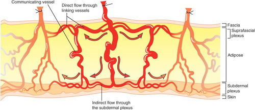 Figure 62.1. Perforators are connected through two mechanisms: direct flow via linking vessels and indirect flow through the subdermal plexus. Communicating branches connect the direct and indirect linking vessels. |
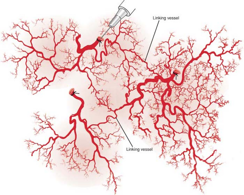 Figure 62.2. Linking vessels connect multiple perforasomes. |
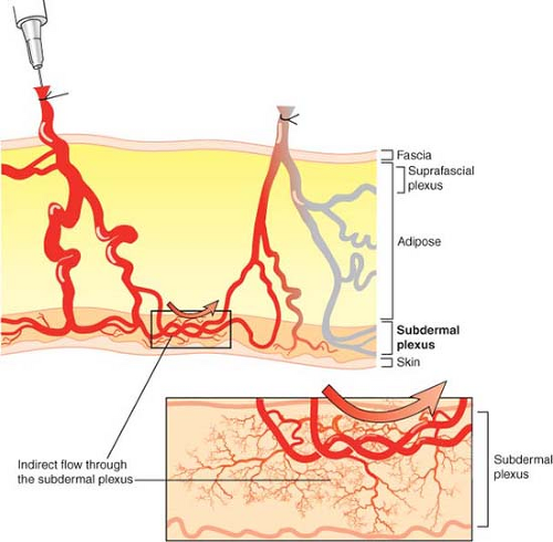 Figure 62.3. Perforators can also be linked to one another by indirect linking vessels or recurrent flow via the subdermal plexus. |
Deep Inferior Epigastric Perforator Flap
Utilization of abdominal tissue for autologous breast reconstruction has been long and widely practiced. It is an ideal source, as most patients who develop breast cancer are at an age when they also have excessive abdominal fat and skin. The DIEP flap evolved from the traditional transverse rectus abdominis myocutaneous (TRAM) flap. Holmstrom first described the free TRAM flap in 1979 for breast reconstruction (21). In 1982, Hartrampf et al. popularized the pedicled TRAM flap, based on the superior epigastric artery (22). However, this has been shown to be the secondary blood supply to the tissue of the anterior abdominal wall (17,18,19,20,21). Currently, the inferior rather than the superior epigastric pedicle plays the dominant role in abdominal tissue transfer in autologous breast reconstruction.
Koshima and Soeda described the inferior epigastric artery skin flap (8), but it was Allen and Treece (23) who first used the DIEP flap for breast reconstruction, which has now become common practice in certain plastic surgical centers.
Anatomy
Like a free TRAM flap, the pedicle of the DIEP flap is the deep inferior epigastric artery that originates from the medial aspect of the external iliac artery just above the inguinal ligament. The deep inferior epigastric artery is the most significant artery supplying the skin of the anterior abdominal wall, with a pedicle of 7.5 to 20.5 cm in length and 3.3 ± 0.4 mm in diameter, with two accompanying venae comitantes in the majority of cases (24). There are 5 ± 2 perforators from the deep inferior epigastric artery concentrated in the periumbilical region. It forms two main intramuscular branches in the majority of cases: the lateral branch gives off a lateral row of perforators in the lateral one third of the muscle, communicating through deep anastomoses with the lower four intercostals, and the medial branch gives off a medial row of perforators in the medial one third of the muscle, which gives off an umbilical branch and then terminates in deep choke vessel anastomoses with the superior epigastric artery above the umbilicus.
Medial Row Perforator Deep Inferior Epigastric Perforator Flap
In our study of DIEP flaps, the mean vascular territory for a medial perforator DIEP flap injected with contrast was 296 cm2 (p < 0.008 when compared to vascular territory of lateral perforator). The branches of the medial row perforator were seen to be directed both laterally and medially and crossed the midline in all cases. The vascular territories of these flaps were more centralized than those perfused by a lateral perforator (Fig. 62.4). Large-diameter linking vessels were found to connect perforators within the same medial row (Fig. 62.5). The
injected medial perforators connected with contralateral medial row perforators (across the midline) through the indirect linking vessels via the subdermal plexus (Figs. 62.6 and 62.7). Moon and Taylor also noted that crossover of the midline is predominantly in the subdermal plexus (25). Medial row and lateral row perforators within the same hemiabdomen were connected via both direct and indirect linking vessels (Fig. 62.7).
injected medial perforators connected with contralateral medial row perforators (across the midline) through the indirect linking vessels via the subdermal plexus (Figs. 62.6 and 62.7). Moon and Taylor also noted that crossover of the midline is predominantly in the subdermal plexus (25). Medial row and lateral row perforators within the same hemiabdomen were connected via both direct and indirect linking vessels (Fig. 62.7).
 Figure 62.4. Three-dimensional computed tomography angiogram of a medial perforator deep inferior epigastric artery flap, anteroposterior view. Perfusion is more centralized. |
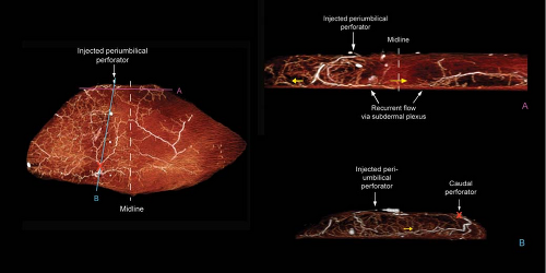 Figure 62.5. Left: Anteroposterior view of a transverse lower abdominal adipocutaneous flap where a medial (periumbilical) perforator was injected with contrast. Top right: Transverse view of flap, corresponding to line A. Perfusion crosses the midline via the subdermal plexus. Bottom right: Sagittal view of flap, corresponding to line B. X marks a perforator caudal to the injected periumbilical one. Yellow arrows show direction of flow. |
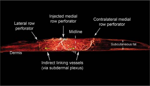 Figure 62.6. Three-dimensional computed tomography angiogram of a medial perforator deep inferior epigastric artery flap, transverse view. Injected medial perforator connected to the contralateral medial row perforator through indirect linking vessels via the subdermal plexus. Yellow arrows show direction of flow. |
When planning a large breast reconstruction, a medial row perforator or a combination of medial and lateral perforators (muscle-sparing TRAM or TRAM flap) should be considered. If a single medial row perforator is selected, the vascular territory is larger and more centralized than a lateral row perforator-based flap. Therefore, both tips of the flap are the furthest away from the medial perforator and are subjected to a higher risk of ischemia (Fig. 62.8). When selecting a perforator for DIEP flap surgery, the largest perforator should be selected. We found in both clinical and cadaver dissections that periumbilical perforators were the most dominant/largest perforators in most cases (Fig. 62.9).
Related posts:
 Follow-Up After Surgery for Primary Breast Cancer: Breast-Conserving Therapy and Mastectomy
 Breast Implants: Materials and Manufacturing Past, Present, and Future
 Reconstruction of the Irradiated Breast
 Perforator Flaps in Breast Reconstruction
 Management of Chronic Postoperative Breast Pain
 The Periareolar Approach to Augmentation Mammaplasty
Stay updated, free articles. Join our Telegram channel

Full access? Get Clinical Tree


