Imaging
A. Bobby Chhabra
Chealon D. Miller
Lindley Wall
Standard radiographs of the hand and wrist include anterior-posterior (AP), lateral, and oblique images. Computed topography (CT) may be used to improve visualization of the articular surface and provide more detail of osseous structures. Magnetic resonance imaging (MRI) is useful to evaluate soft tissue structures and is often used to evaluate for occult fractures, osteonecrosis, injuries of the triangular fibrocartilage complex (TFCC), and injuries of the scapholunate and lunotriquetral ligaments. Initial evaluation of any hand and wrist pathology should begin with plain radiographic imaging (x-rays). If initial x-rays are negative, advanced imaging is ordered based on physical examination findings.
I. Hand and Wrist Anatomy
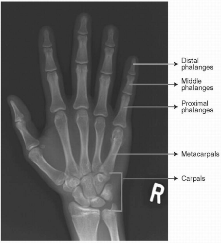
Bones of the hand and wrist (Fig. 2.1)
The hand is made up of five distal phalanges, four middle phalanges (the thumb does not have a middle phalanx), five proximal phalanges, and five metacarpals. The AP, lateral, and oblique radiographs are the most common views used to diagnose pathology of the hand.
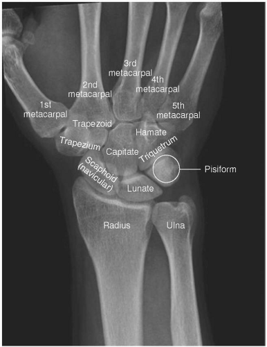
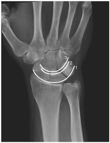
The wrist comprises eight carpal bones in two rows (Fig. 2.2). The wrist is defined as the area beginning 3 cm proximal to the radiocarpal joint and terminates at the carpometacarpal (CMC) joints. The bones of the hand and wrist include the radius, ulna, scaphoid, lunate, triquetrum, pisiform, trapezium, trapezoid, capitate, and hamate. AP and lateral views are used most often to evaluate wrist pathology.
Ligaments of the hand and wrist
The wrist joint comprises an articulation between the distal radius and the distal ulna, and an articulation between the distal radius and ulna with the bones of the carpus. There are extrinsic (originate or insert outside of the carpus) and intrinsic (originate and insert within the carpus) ligaments that support these joints.
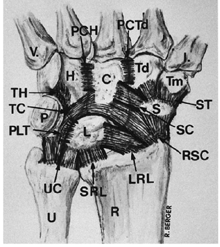
The important extrinsic volar wrist ligaments form a double “V” pattern and include the radioscaphocapitate ligament, and long and short radiolunate ligaments ulnolunate, ulno-triquetral, (Fig. 2.3). Other ligaments on the volar side include the triquetralcapitate, triquretralhamate, lunotriquretral, scaphocapitate, scaphotrapezium, and capitotrapezoid. These ligaments are important from a clinical standpoint, but not from an imaging standpoint.
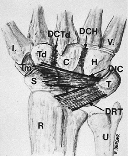
The dorsal wrist also contains ligaments that are important for wrist stability (Fig. 2.4). The major dorsal wrist ligaments are the dorsal intercarpal ligament and the dorsal radiocarpal ligament. Similar to the volar wrist ligaments, these are important clinically, but not from an imaging standpoint.
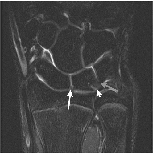
The intrinsic wrist ligaments are situated within the proximal and distal rows. The scapholunate and lunotriquetral ligaments are the strongest ligaments in the proximal row on the dorsal and volar aspects of the wrist, respectively. The bones of the distal row are tightly linked to each other and to the metacarpals (Fig. 2.5).
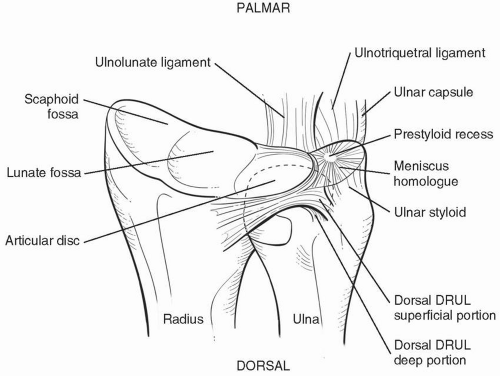
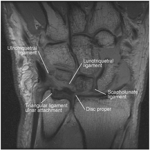
The TFCC consists of an articular disk, meniscus homologue, ulnocarpal ligament, dorsal and volar radioulnar ligament, and extensor carpi ulnaris sheath (Figs. 2.6 and 2.7). It originates from the medial border of the distal radius and inserts into the base of the ulnar styloid. It separates the distal radioulnar joint (DRUJ) from the radiocarpal joint.
Muscles and tendons of the wrist and hand
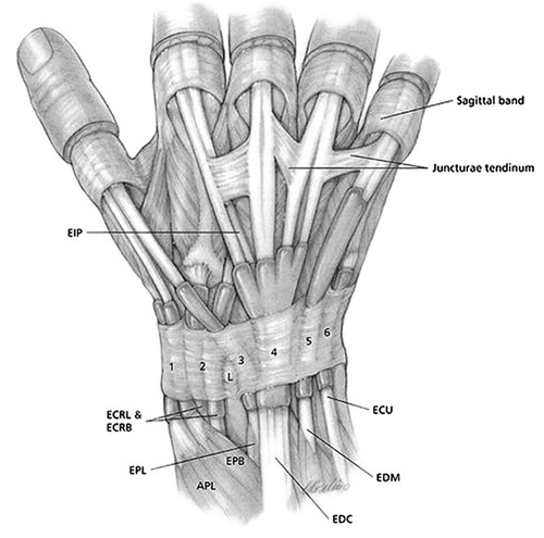
There are six dorsal compartments of the wrist containing tendons that arise from separate muscle bellies in the forearm (Fig. 2.8).
Extensor Compartment 1: Abductor pollicis longus and the extensor pollicis brevis (EPB)
Extensor Compartment 2: Extensor carpi radialis brevis and the extensor carpi radialis longus.
Extensor Compartment 3: Extensor pollicis longus.
Extensor Compartment 4: Extensor digitorum comminus and the extensor indicis propius.
Extensor Compartment 5: Extensor digiti minimi.
Extensor Compartment 6: Extensor carpi ulnaris.
II. Anterior-Posterior and Posterior-Anterior Views of the Hand and Wrist
The AP view of the hand and wrist for the evaluation of hand and wrist injuries is obtained with the volar surface of the hand facing the x-ray beam. The beam passes from the volar surface to the dorsal surface.
The posterior-anterior (PA) view of the hand and wrist is obtained with the volar surface of the hand facing the table (away from the x-ray beam). The beam passes from the dorsal surface to the volar surface (Figs. 2.9 and 2.10).
The volar surfaces of most carpal bones are narrower. These bones are best profiled with AP rather than PA views of the wrist because of improved alignment of the periarticular cortices with the diverging x-ray beam.
The ulnar styloid is helpful in determining the direction in which the films were obtained. In the standard AP view, the ulnar styloid is located centrally over the distal ulna (because the view is taken with the forearm in supination), whereas in the PA view of the wrist, the ulnar styloid is located ulnarly on the ulnar head (because the forearm is in neutral rotation).
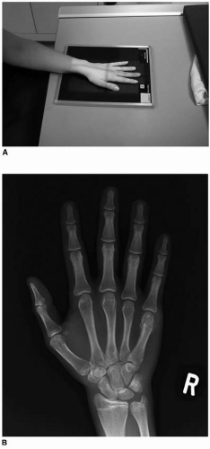
Figure 2.9 A: Technique for obtaining zero rotation. Note that the shoulder and the forearm are the same distance from the floor. PA view of the hand. B: Radiograph for PA view of the hand.
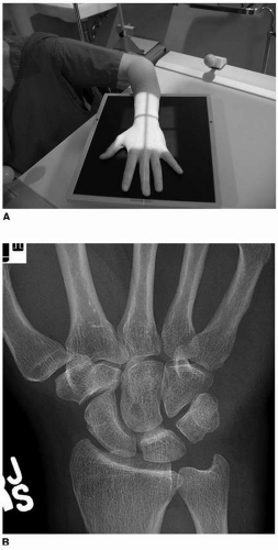
Figure 2.10 A: Technique for obtaining zero rotation PA view of wrist (note the shoulder is abducted 90 degrees (parallel to the ground) and the elbow is flexed 90 degrees)
A zero rotation view is used to determine the true ulnar variance. This is obtained with the shoulder abducted 90 degrees, the elbow flexed 90 degress, and the wrist in neutral position as illustrated in Fig 2.10A.
Stay updated, free articles. Join our Telegram channel

Full access? Get Clinical Tree


