Viscosity (< 5,000 centipoise)
b. Impellers for Liquids of Low and Medium Viscosity
d. Pumping Capacity and Velocity Head
g. Flow Patterns: Fluids of High Viscosity
h. Impeller Types and Mixers for High-Viscosity Fluids
13.1.3.2 Wet Systems – Multiphase Systems
e. Emulsion Processing Equipment – Mixing
f. High-Shear Mixers and Dispersion Equipment
h. Continuous High-Pressure Homogenizers and Mixers
i. Processing of Water in Silicone Emulsions
13.1.3.3 Wet Systems—Liquid–Solid Systems
c. Filling – Low-Viscosity Products
(Lotions, Toners, Liquid Makeups)
d. Filling – High-Viscosity Products
(Creams, Mascaras, Masks)
e. Filling—Traditional Lotion Products
f. Filling – Shear-Sensitive Products
g. Filling Shampoos, Conditioners,
Cleansers—Products That Aerate
i. Warm and Hot Fills—Creams and Dispersions
j. Warm and Hot Fills—Godet Products
k. Warm and Hot Fills—Lipsticks, Lip Balms, Suppositories
l. Antiperspirants and Deodorants
c. Alternatives to the Hammer Mill
e. Powder Grinds for Creams and
Lotions Batches—Dry Mix
13.1.7.1 Wet Continuous Process
a. Emulsion Products Requiring Cooling
d. Scale-Up of Continuous Systems
e. Production Design Considerations
13.1.7.2 Dry Continuous Processing
This chapter begins by providing a brief understanding of the more important unit operations, namely mixing, heat transfer, and mass transfer. This is followed by a treatment of equipment, procedures, and principles commonly used in the cosmetics industry to manufacture and fill both wet and dry products, including some newer approaches to the emulsion system concepts. Knowledge of this background, combined with time spent in both the pilot and manufacturing plants, will equip the effective formulator to carry out successful new product introductions.
Formulating cosmetic and personal care products is an ancient art. Originally, these products contained ground minerals in an oil or grease. They were initially used by men to exaggerate their features during battle, to conduct tribal ceremonies, and to differentiate different tribes or clans. The use of cosmetics by women began in ancient Egypt. Color products accentuated facial features; plant and animal essences provided a scent to the hair and body (minimizing body odor); and greases and oils were used to treat the skin. Skin care did not really change over the years and typically involved the application of natural oils or glycerin and rosewater preparations.
A Brief Chronological Survey
The first widely used cosmetic dates back to AD 200 when the Greek physician, Galen, published a formula that contained only rose water, beeswax, and olive oil. This formula remained essentially unchanged until the late 1800s, when borax was added to the basic formula to form a simple cold cream preparation. The principal cleansing agent at the time was a lye-based soap made by mixing potash or lye with animal or vegetable-based fats. The art of soap-making became more refined throughout the second millennium.
The era of modern cosmetics emerged in the 1940s with the widespread use of synthetic surface-active agents. These materials, commonly called surfactants, modified the surface tension of the oil and water phases and enabled the formulator to mix them together to form a composition that was stable for at least the commercial shelf life of the product. These preparations were called emulsions and the surface-active materials used to form them were called emulsifiers. Personal care products continued to evolve throughout the latter part of the 20th century. Raw material manufacturers improved aesthetic sensations through the use of new, more refined natural oils and synthetic emollients, thereby allowing product forms to become more diverse. Traditionally skin care products were moisturizers. They were used to treat dry skin by plasticizing and softening the hard, rough, tight, scaly manifestations of damaged skin.
In the late 1960s and early 1970s functional skin treatment products emerged. Product performance expanded beyond the amelioration of superficial dryness, and benefits evolved to a higher therapeutic level. The boundary between cosmetics and dermatological drug products began to blur. Problems such as aging, uneven skin pigmentation, slack skin, cellulite, sensitive skin, oily skin, and dryness were identified and agents were sourced, or developed, to address these conditions—most as cosmetics, some as dermatological (drug) products. These skin disorders were often associated with conditions such as sunburn, acne, or the need for topical analgesia, etc. The personal care market started to borrow from the latest advances in medical research. Processing these new formulations has become even more important to maintain the required aesthetics and stability required by the consumer.
In the 40 years since the late 1970s, formal chemical engineering concepts began to be introduced into the manufacture of cosmetics and personal care products. There appeared a schism between formulators (chemists) and process engineers (usually chemical engineers). Their scholastic training overlapped, but communication within an organization was often far from perfect. Yet, while these disciplines can be very diverse, the successful development of commercial cosmetics requires a smooth transition from bench to pilot to full-scale production.
Within the recent past, OTC (over-the-counter drugs) protocols have added multiple layers of regulations and paperwork to be handled from both R&D and Production. Anti-dandruff shampoos, antiperspirants, and sunscreen products are much more common. Also included in these changing times is the emphasis on “organic” and “natural”—two words that indicate potential issues related to raw materials (consistency), formulation (control of aesthetics), and process (control of the uncontrolled).
In this chapter, we focus primarily on the chemical engineering principles without which pilot and full-scale manufacture would be nonexistent. In the spirit of Harry’s long history of explaining concepts in simple terms, we have taken the approach of examining the areas most important to gaining a true understanding of what it takes, at the full-scale production end of the process, to generate mass-scale production of products creatively generated in the laboratory—both through the creative thinking of “ingredient-seekers” to formulators to (and from) marketers. We seek to acknowledge all of the people who contribute to making new products and brands successful.
We begin with Unit Operations, the heart of understanding the basics of full-scale production.
When studying scale-up operations, wherever they originate, and no matter how complex, one considers a limited number of physical phenomena. These are separated into discrete yet interdependent events called “unit operations.” The manufacture of cosmetics can be described in terms of four operations:
- • Fluid Flow / Mixing
- • Heat Transfer
- • Mass Transfer and
- • Filtration
All phases of cosmetic manufacture involve aspects of each.
Fluid Flow attempts to define operations involving movement of fluids and solids exhibiting fluid-like behavior. Mixing and agitation, pumping, and metering of liquids are typical operations studied in fluid flow.
Heat Transfer involves the movement of thermal energy in a gradient from areas of higher temperature to areas of lower temperature. Heating and cooling of cosmetic bulk by conduction, convection, and radiation are studied.
Mass Transfer operations define phenomena that involve movement of components of a mixture in a concentration gradient from areas where the concentration of a component is high to areas where it is lower. Cosmetic processes can make use of mass transfer by absorption (e.g., addition of binder to a cosmetic powder) and diffusion (e.g., migration of an active ingredient). The formation of an emulsion itself can be described in terms of mass transfer.
Filtration is not usually a unit operation of major importance in cosmetics manufacture except in the production of spirituous preparations (astringents/toners, colognes, aftershaves, and perfumes). It is possible to regard filtering as unmixing, and certainly the flow characteristics of the filtered product are again of prime importance. Filtration is usually included in the process to ensure clarity. The use of sub-micron filters for the sterilization of water is discussed elsewhere in this chapter.
Each of these four unit operations involves mathematical treatments that are, perhaps, inappropriate for this book and not pertinent to our practical use of the operations. Their theoretical treatment can be found in any good chemical engineering textbook, such as Unit Operations of Chemical Engineering by McCabe and Smith.
Mixing and heat transfer are the most critical operations and will be discussed in some detail [1].
The subject of bulk cosmetics manufacture revolves around satisfactory mixing. There are several types of mixing employed as indicated in Table 13.1 below.
Table 13.1: Scope of mixing operations within the cosmetics industry
Type of mixing | Examples |
Gas/Liquid (a) Cohesive (b) Segregative | (i) Dispersion (aeration and gasification) (i) Deaeration or degassing |
2. Liquid/Liquid (a) Cohesive (b) Distributive (B) Immiscible (a) Cohesive (b) Distributive (c) Segregative | (i) Chemical reactions (formation of salts from acid and base) (ii) Blending (spirituous preparations, clear lip gloss products) (iii) Pumping (low-viscosity system) (i) Blending (flow controlled) (ii) pH control or soap formation from fatty acid and base (iii) Pumping (high-viscosity system) (i) Emulsion formation (dispersion–addition rate is not critical) (i) Emulsion formation (dispersion–addition rate is critical) (i) Coalescing / Settling (phase separation) |
3. Solid/Liquid and Liquid/Solid (b) Distributive (c) Segregative | (i) Dissolution (of water-soluble dyes, preservatives, powder surfactants, etc.) (ii) Suspensions and dispersions (mascara, pigments in castor oil and in other liquids) (iii) Hot pour products (lipsticks, etc.) (i) Controlled addition of liquid binders or actives to powders (i) Filtration, sedimentation, decantation |
4. Solid/Solid (b) Cohesive | (i) Free flowing powders discharged from hoppers, etc. (i) Face powders, eye shadows, and all dry mixing |
Types of mixing:
Cohesive mixing – natural or forced combining of particles during blending
Segregative mixing – natural or forced separation of particles during blending
Distributive mixing – controlled or uniform diffusion of particles during blending
Table 13.1 represents a convenient way of classifying the mixing processes most commonly found within the cosmetics industry. Almost every cosmetic manufacturing process includes at least one mixing operation and often more than one type is involved. For example, the manufacture of a pigmented emulsion-based foundation cream may include:
- (i) Preliminary dry blending of pigments and excipient (type 4b- i).
- (ii) Dissolution of oil-soluble and water-soluble materials separately in their appropriate phase (type 3a- i and type 2Aa- ii).
- (iii) Dispersion or suspension of pigments in the oil or water phase (type 3a- ii).
- (iv) Mixing of the two phases to form an emulsion, possibly with the formation in situ of soap as part of the emulsifier (types 2Ba and 2Bb).
- (v) Adjustment of pH (type 2Ab- ii).
- (vi) Deaeration of the bulk (type 1b- i).
- (vii) Shade matching (type 3a- i or -ii and iii).
- (viii) Pumping into a storage vessel (type 2Ab- iii).
Not only are all these operations different from each other, but at each stage the characteristics of the bulk are quite different and require a different set of processing characteristics to achieve an optimal economic process. Not surprisingly, the optimum is rarely achieved throughout the process.
The subject of pumping is not clearly separated from that of mixing since the pumping process implies the forced flow of product. Any flow will naturally introduce an element of mixing if the product is not already homogeneous. Further, since flow is a common element of both processes, the same product characteristics (e.g., rheological behavior) must be taken into account in each process. Different types of pumps provide different quantities of shear to the product and thus provide different degrees of mixing. The “standard” in the industry is the positive displacement pump, which imparts little shear and thus little mixing to the product. The centrifugal pump works similarly to a propeller mixer in a frame. This pump can impart a great deal of shear and produce vigorous mixing. It is typically used with lower-viscosity materials.
Mixing can only occur by relative movement between the particles of the constituent components. Three basic mechanisms for achieving this relative movement are bulk flow, convective mixing, and diffusive mixing.
- • Bulk flow (which includes shear mixing, cutting, folding, and tumbling) occurs in pastes and solids when relatively large volumes of mixture are first separated and then redistributed to another part of the mixing vessel.
- • Convective mixing involves the establishment of circulation patterns within the mixture (e.g., propeller mixing).
- • Diffusive mixing occurs by particle collisions (e.g., thermal diffusion and concentration diffusion). In miscible liquids of sufficiently low viscosity, the thermal energy of the constituent molecules may be enough to achieve a good mixing by thermal diffusion without additional energy.
It is incorrect to assume, however, that the relative movement between mixture particles brought about by these mechanisms always results in an improved mixture quality or homogeneity. Many mixing problems arise from the tendency of mixture particles to segregate or aggregate during attempts to mix them, particularly with powders.
Segregation is defined as the preference of the particles of one component to be located nonrandomly in one or more sites in a mixture. The size of the nonuniformities in an imperfect mixture is sometimes referred to as the “scale of segregation” and the difference in composition between neighboring volumes is the “intensity of segregation.” Segregation is fortunately not a major problem in cosmetics manufacture although it does manifest itself occasionally (e.g., the flotation of pigments during lipstick processing).
Aggregation is defined as the preference for the particles of one component to join with another component or components and then travel through the batch as a group. The aggregation can be physical (mixing of different-viscosity materials), physical bonding (powder agglomerations), or Van der Waals attractive forces leading to agglomeration of an emulsified droplet forming a loosely bound cluster of many individual droplets that may be shear sensitive and therefore produce smaller clusters at higher shear rates and pseudoplastic rheological behavior (i.e., viscosity decreases with increasing shear rate). To best control the distribution of some raw materials, aggregation may be required; cohesive powders may be included in the formula or the process may be used to develop an aggregation that is easily controlled. Surfactant/emulsifier selection and concentration can control the degree of agglomeration and final product stability/behavior.
Some products can be made without heating but these systems preclude the use of higher melting-point materials that can add richness to the aesthetics of the final product. Further, if the rate of mixing is high, there is a chance that air can be entrapped in the emulsion. This phenomenon causes an undesirable decrease in the specific gravity of the product and an artificial increase in product viscosity. Any variability in processing can lead to a range of undesirable rheological and textural properties. This issue can occur even if the formulation is not modified.
The term “product by process” is well known in the patent art and describes the above-stated phenomenon. If two or more formulators prepare the same product, the resulting compositions may vary considerably. This variation can occur even though each person utilized the same lots of raw ingredients. This occurs because it may be very difficult to exactly reproduce all of the processing parameters used to make an emulsion, for example. If any of the processing variables are modified unexpectedly, particle size variations may occur, or the crystalline properties of the emulsion can be compromised. Table 13.2 is a chart containing the results from an experiment to determine the effect of processing on the final properties of a 5% petrolatum-containing cream. All preparations contained the same lots of ingredients. The data demonstrate that the viscosity and specific gravity can vary dramatically depending upon the processing parameters employed to make the batch.
Table 13.2: Petrolatum Cream (5%) – Standard Emulsion Test Results
Sample 1: Optimum manufacturing procedure | ||||
Sample 2: Overheated phases | ||||
Sample 3: Forced cooling | ||||
Sample 4: Ambient cooling | ||||
Sample 5: Paddle mixing | ||||
Sample 6: Rapid homogenization | ||||
Sample 7: Under heated phases | ||||
| ||||
Sample | Specific Gravity | Initial Viscosity (cP) | Viscosity (cP) 24 Hr @ 25°C | Viscosity (cP) 24 Hr. @ 50°C |
1 | 0.912 | 99,970 | 140,580 | 26,560 |
2 | 0.937 | 85,910 | 93,720 | 29,690 |
3 | 0.952 | 93,720 | 109,340 | 29,700 |
4 | 0.941 | 51,550 | 96,840 | 131,200 |
5 | 0.959 | 62,480 | 85,910 | 78,100 |
6 | 0.803 | 112,460 | 124,960 | 20,620 |
7 | 0.931 | 51,550 | 96,840 | 20,600 |
Note: Viscosity measurements were taken with a Brookfield LVT model viscometer | ||||
There is foreseeable uncertainty at the “bench” level in the laboratory that a typical 500-gram to 2000-gram laboratory preparation will translate well to a manufacturing environment. This concern is often well founded. To deal with the vagaries of scale-up, the product may be subjected to a wide range of processing variations in order to optimize the conditions of manufacture. Products made at each level of scale-up are typically subjected to accelerated stability testing in order to ensure the integrity of the product for its anticipated shelf life. A significant alteration to the past “tried-and-true” systems or the development of an entirely new system is often laced with unknown issues that can severely jeopardize the introduction (timing) of a new product.
Apart from the “dry” powder processing discussed later, the processes listed in Table 13.1 involve mostly liquids present in sufficiently large quantities as to impose fluid characteristics on the mixture. Although there are similarities between the flow of powders and the flow of liquids, it is easier to set up and sustain flow patterns in liquids. This makes liquid mixing processes easier to perform with a much larger variety of equipment from which to choose.
However, even for liquids the science of mixing has not yet been sufficiently developed to enable the optimal mixer to be designed for a given process from purely theoretical calculations. Much of the knowledge we have is empirical and has been accumulated from trial-and-error practical experience. Application of Computational Fluid Dynamics (CFD, a method of mathematically modeling moving systems) promises to enhance the theoretical understanding of how forces are transmitted through a fluid by a given mixer design. The use of tomography in specially designed laboratory and pilot systems (glass or clear plastic vessels) have provided actual measurements that can be used to verify CFD results and designs. Most of these are specialized, controlled systems using plastic beads or liquid latex spheres moving through a water or a glycol system. The liquid makes the movement easy to see and measure using lasers. Several agitation blades have been developed, modified, and improved since the 1990s using this technology. CFD now allows the models to be developed using computers alone. 3D printers can then be used to create the test pieces to confirm the designs.
By definition, fluid mixing occurs when an applied force (e.g., a moving mixer blade) creates a velocity gradient, also known as the rate of shear, in the fluid. The “layers” or “particles” that make up the fluid are moving at different velocities relative to each other while the mixing blade is exerting the force. On the other hand, agitation occurs when the fluid particles and blade are moving at the same velocity, much like droplets of cream swirling around in a cup of coffee. In the coffee and cream example, mixing does not occur until blade speed is increased sufficiently to create a velocity gradient that breaks up the cream droplets into a fine dispersion that we know as “café-au-lait.”
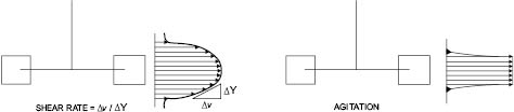
Figure 13.1: Shear rate and agitation profiles [2]
Not only is there a great variation in the physical form and properties of substances that the cosmetics industry needs to mix, but there is also a divergence of purpose. As indicated by Table 13.1, it is convenient to consider two cases separately; the first, in which the liquid components are all mutually soluble (miscible liquids), and the second, in which some or all of them can coexist as separate phases (immiscible liquids, at best partly soluble in each other).
Some mixing operations involve simple blending of miscible ingredients, for example the blending of color solutions into miscible liquids and the blending of oils, alcohol, and water in perfumes and colognes. Mixing of miscible liquids represents the simplest mixing operation in cosmetics manufacture and is achieved by developing bulk flow throughout the vessel. On the other hand, the formation of an emulsion from two immiscible phases, the suspending of a gelling agent, and the distribution of pigment agglomerates in a viscous liquid all require hydraulic shearing to break up the constituents of the mixture into finer particles during the mixing process. For this reason, such mixing is referred to as high-shear mixing in order to distinguish it from simple blending.
On the industrial scale, mixing occurs as the result of forced bulk flow within the mixing vessel. Two types of flow can be distinguished—laminar and turbulent.
Laminar flow occurs when the fluid particles move along streamlines parallel to the direction of flow. The only mode of mass transfer is by molecular diffusion between adjacent layers of fluid (Brownian motion). Heat transfer is accomplished by the same type of mechanism—conduction from layer to layer.
In turbulent flow, the fluid elements move not only in parallel paths but also on erratic and random paths, thus producing eddies which transfer mass from one layer to another. For this reason, turbulent mixing is rapid compared with other mixing mechanisms. Heat transfer is also influenced by forced convection—moving heat from higher- to lower-temperature areas along eddies created by turbulent mixing.
When a liquid at rest is slowly stirred the flow is laminar, but as the liquid’s velocity increases flow will eventually become turbulent. A valuable aid in describing the critical point at which laminar flow becomes turbulent is due to Osborne Reynolds who, in 1883, first characterized turbulence. The dimensionless number that bears his name, NRe, can be calculated for an impeller mixing in a tank as follows:
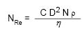
Where Nre = Reynolds Number In Dimensionless Units
D = Diameter Of The Impeller In Centimeters
N = Impeller Speed In Revolutions Per Minute
ρ = Density Of Liquid In Grams Per Cubic Centimeter
η = Viscosity Of Liquid In Centipoise
C = Conversion Constant Of 1.67 × 10⁻⁴
Equation 13.1 Reynolds Number
Experience has shown that the onset of turbulence occurs at Reynolds Numbers above 2,000. For fully developed turbulence, Reynolds Numbers greater than 10,000 are required and these higher values are found in many cosmetic mixing processes. As shown in Equation 13.1, it becomes more difficult to achieve turbulence as the viscosity (η) increases. Between 1000 and 10,000 centipoise, the viscosity range of many cosmetic products, turbulent flow can be achieved without the need for an excessive amount of power. For highly viscous creams and pastes, mixing raises certain problems since the flow pattern in the mixer is invariably laminar. Under these circumstances, distributive mixing (cutting and folding) is more applicable than turbulent mixing. Turbulence not only provides rapid mixing but also influences dispersion (mass transfer) and heating/cooling (heat transfer).
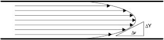
Figure 13.2: Velocity gradient of flow through a pipe
As can be seen by examining flow through a pipe Figure 13.2, there is a velocity gradient between the layers of moving liquid. A similar gradient can be found with the movement of all materials. When Newtonian (or ideal) liquids flow, the relationship between the force causing the movement (F) and the velocity gradient (ν) between the layers of moving liquid is as follows:
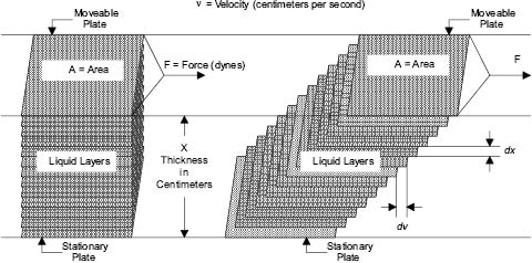
Figure 13.3: Newtonian flow [3]
F/A is commonly referred to as the “shear stress” and the velocity gradient (ν) as the “rate of shear.” Assuming an ideal fluid, as velocity of flow increases, so does shear stress. This is the force that breaks up the weak bonds holding together pigment aggregates or other immiscible phases into droplets. Shear forces are also produced when liquids flow under laminar conditions, but under these circumstances the energy used to generate flow is dissipated largely as heat. During turbulent flow, the energy is dissipated in disorder; eddies are produced whose size and intensity depend upon the viscosity of the liquid and upon the force F. For a liquid of a given viscosity, the droplet size of an emulsion or the fragmented size of dispersed pigment agglomerates depends primarily on the energy input from the agitator, the velocity gradient, and the nature of the forces holding together the disintegrating entities. Unfortunately, the simple model shown in Equation 13.2 has limited application in cosmetics manufacture.
F = η × A × ν
Where F = Force in gram-centimeters per second squared
η = Coefficient of Viscosity of Liquid in gram per centimeter-second squared
A = Cross-sectional Area of the liquid in square centimeters
ν = Velocity Gradient in centimeters per second
Equation 13.2 Force relationship to viscosity
The majority of products exhibit non-ideal (non-Newtonian) behavior, which can often be more appropriately described by the Equation 13.3.
F = (ηapp) n × A × ν
Where: F = Force in gram-centimeters per second squared
ηapp = Apparent Viscosity of Liquid in gram per centimeter-second squared
n = exponent
A = Cross-sectional Area of the liquid in square centimeters
ν = Velocity Gradient in centimeters per second
Equation 13.3 Force relationship to apparent viscosity
In the case where the exponent, n, has a value between 0 and 1, the type of behavior is “pseudoplastic.” The basic difference between materials exhibiting this property and ideal or “Newtonian” fluids is illustrated in Figure 13.4. As can be seen, pseudo plasticity is manifested by a decrease in viscosity with increasing shear rate at constant temperature. Many cosmetic liquids exhibit this behavior, especially emulsions and suspensions of particles 1 µm or less in size. Pseudoplastic viscosity loss is usually reversible; since apparent viscosity decreases as the shear rate increases and then increases along the same path as the shear rate is decreased; thus, when left unstirred long enough, the fluid will recover some or most of its original viscosity. The magnitude of the pseudoplastic effect is variable with the identity of the fluid, although a fall in viscosity of 25% when the rate of shear is doubled is not unusual.
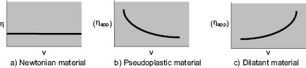
Figure 13.4 Rate of shear (ν) plotted against viscosity (h) or apparent viscosity (ηapp)
Three other types of rheological behavior are also worth noting, although they are less frequently encountered in cosmetics processing. A truly “plastic” fluid exhibits viscosity versus shear rate curves similar to those of pseudoplastic materials, but a certain force must be applied before any shear (or flow) takes place. “Dilatant” materials show the opposite effect, viscosity increasing with shear rate, Figure 13.4 c. The term “thixotropic” is often used erroneously to describe pseudoplastic behavior. Thixotropic liquids exhibit a decrease of viscosity with time at constant shear rate, not with increasing shear rate as Figure 13.4 b shows for a pseudoplastic material. However, like the pseudoplastic material, the thixotropic liquid usually recovers most of its original viscosity after the mixing force is removed. An excellent overview of the various rheological behaviors and both their mathematical characterization by empirical constants as well as their useful graphical characterization can be found in Part 1 of the Rheology Modifiers Handbook by David B. Braun and Meyer R. Rosen, 1999, William Andrew Publishing/Elsevier Publishing. The authors, well familiar with the discomfiture of mathematics in the chemist’s realm have provided graphical representations of the various equations and pointed out the value of what they term “Practical Rheology,” where the empirical constants in the many equations can be usefully related to performance parameters of cosmetic and personal care products.
In the mixing of fluids, all three mixing mechanisms—bulk flow, turbulent diffusion, and molecular diffusion—are usually present. As viscosity increases, however, and turbulence becomes more difficult to establish, the parts played by turbulent and molecular diffusion become less important. Mixing equipment can be divided into two categories, depending on whether or not turbulent conditions prevail, as follows:
Table 13.3: Types of mixing equipment
Laminar Shear / Distributive Mixers | Turbulent Mixers |
Helical Screw / Ribbon Blenders | Turbine-Agitated Vessels |
Two-Blade Mixers | Pipes |
Kneaders | Jet Mixers |
Extrusion Devices | Sparged Systems |
Colanders | High-Speed Shear Mixers |
Static Mixers: Low NRe | Static Mixers: High NRe |
Contra-Rotational and Planetary Blades at Low Speed | Contra-Rotational and Planetary Side-Wiping Blades at High Speed |
Control of mixing parameters and of the rheological characteristics of the bulk allows the manufacture of products with optimum homogeneity and stability. Heat and mass transfer are functions of the mixing process. The same mixing parameters that achieve ingredient homogeneity also influence heat and mass transfer. Good heat-transfer and good mass-transfer are both consequences of good mixing.
The topic of heat transfer in cosmetic operations does not require mathematical treatment as much as methodologies for its use and control in processing and scale-up. Heat can be used to one’s advantage in a formulation. One must be aware of the fact that what can be done on the laboratory bench may not be achievable in production. The process team must be aware of the capabilities of available production-sized kettles and of the amount of heating and cooling capacity available to them.
The manufacture of most cosmetic creams and lotions involves the formation of an emulsion in which an oil and/or wax phase is combined with a water phase. This combination is made most often at higher temperatures. The even distribution of temperature is of major importance in the formation of a good emulsion. Control of the rates of heating and cooling is required in order to scale properly from bench to production and if the formulation is to be reproducible from batch to batch.
The relationship of heat and mass transfer to mixing is similar and can be treated as analogous phenomena. The degree of heat transfer depends upon a relative temperature difference (temperature gradient), which provides the driving force toward equilibrium. Equilibrium means that the temperature difference between transfer medium and product is zero. In reality, the maintenance of a gradient is required to meet the desired endpoint in heating or cooling the product, namely the “set point temperature.” At this temperature we want to stop the heating or cooling process, and this is done by making the gradient zero.
The mathematical relationship between heat transferred (Q) and temperature gradient (∆TLM) is expressed below.
Q = Uo Ao ∆TLM
Where: Q = Heat transfer in watts
Uo = Overall heat transfer coefficient in watts per square meter °C
Ao = Heat transfer area in square meters
∆TLM = Log Mean Temperature gradient between the product and the heat transfer fluid (difference) in °C
Equation 13.4 Heat transfer
∆TLM takes into account the multiple heat transfer losses in the process system. The amount of heat transferred is directly proportional to the size of the temperature gradient, the contact area between heat transfer surfaces, and the magnitude of the heat transfer coefficient.
Uo is composed of a number of factors and is expressed as follows:
Where: Uo = Overall heat transfer coefficient in watts per square meter °C
Hc = Individual heat transfer coefficient between the process fluid (the product) and surface—based on the area and ∆t (temperature gradient) between the surface and the fluid—in watts per square meter °C
HdC = Individual heat transfer coefficient between the process fluid and surface— when that surface is fouled—in watts per square meter °C
Xw = Thickness of vessel wall in meters
Kw = Thermal conductivity of vessel wall in watts per meter °C
HdH = Individual heat transfer coefficient between the heat transfer fluid (steam or cold water) and surface—when that surface is fouled by scale—in watts per square meter °C
HH = Individual heat transfer coefficient between the heat transfer fluid (steam or cold water) and surface—based on the area and ∆t (temperature gradient) between the surface and the fluid—in watts per square meter °C
Equation 13.5 Heat transfer coefficient
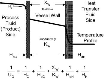
As the individual heat transfer coefficients increase, the overall heat transfer coefficient (Uo) increases. Fouling of either surface decreases the Uo. The fouling that occurs on the heat transfer fluid side of the vessel is usually caused by boiler steam scale or scale from untreated cooling water. This can be corrected by regular cleaning of the vessel jacket, and by use of water additives to minimize scaling.
The fouling that occurs on the process fluid side of the vessel is caused by buildup of the product due to its own viscosity and lack of turbulence (mixing) which makes this “boundary layer” thicker, preventing good heat transfer. The factors HdH and HdC are referred to as “film coefficients.” There are thin layers of fluid that are in immediate contact with the surfaces of the vessel, both on the process side and the heat transfer fluid side. These thin layers represent the “film,” which is essentially at rest. The film coefficient is a measure of the thermal conductivity through this resting fluid.
The importance of mixing as a unit operation is clearly demonstrated by its effect on the product film coefficient, HdC. Higher mixing decreases the thickness of this film layer and permits more rapid heat transfer between the surface of the vessel and the bulk product. During heating, the film can be lower in viscosity than the product, which will improve heat transmission. It is during cooling that the product is subject to a significant decrease in heat transmission due to the increase in viscosity at the cool surface of the vessel. The mixing speed may need to be increased in order to produce the turbulence necessary to make the film thinner so that the bulk can be cooled at a satisfactory rate. The increased shear may be detrimental to the product, which may force a tradeoff between cooling rate and shear rate. A side-wiping agitator can remove this film and replace the cold bulk with warm fresh bulk to be cooled. The removal of the cold layer is of prime importance in providing the proper shear in mixing as well as the specified cooling rate. The relationship between mixing and heat transfer is important information needed for scale-up.
The mass transfer coefficient has a mathematical form similar to the heat transfer coefficient. Its units are in kilogram moles per square meter second in the MKS system. Qualitatively, it is a measure of how much mass is transferred per unit of available surface per second. The heat transfer coefficient is a measure of how much heat is transferred per unit of available surface per second. The driving force for heat transfer is the temperature gradient, ∆T. The driving force for mass transfer is ΔC, the concentration gradient. Mixing influences both in the same way. The formulation team must consider both when developing and scaling a process.
4. Types of Reactors and Their Use in Cosmetics
The most frequently used “reactor” in the cosmetics industry is the CSTR, or continuous stirred tank reactor. This is typically a jacketed stainless-steel vessel with agitation provided by propeller blade, anchor blade, side-wipe, homogenizer, or any combination of these. This type of reactor is used in batch processing. Jacketing the vessel allows a heat transfer medium (cooling water, glycol, steam, hot water, etc.) to circulate. Heat transfer is accomplished by conduction from the inner surface of the vessel, which is heated or cooled by the medium, to the batch. Mixing the batch in the vessel increases the efficiency of heat transfer by forced convection. In batch processing, all raw materials are added to the vessel in a specified order, and the reaction mixture should be homogeneous after each operation. Ideally, each incremental sample of the batch, from any location, should be the same as all others. Proper mixing will ensure homogeneity of the batch (mass transfer) as well as efficient heating or cooling.
In semi-continuous or continuous processes, it is more common to use a “plug flow reactor.” Also called a pipeline reactor, it resembles just that. Unlike the CSTR, the contents of the pipe are not homogeneous throughout the length. Each incremental cross-section of the pipe is different in concentration (contents), and in temperature, from all others. Heat transfer in this type of process is attained by use of a jacket around the pipe similar to the CSTR. Increments of the pipe are heated or cooled as required by the process. As each increment, or plug, moves along the pipe it is subjected to a different set of concentration and temperature conditions. Each increment is homogeneous within itself, but is different from all others along the pipe.
Batch reactors are suitable for use in small-scale operations using expensive raw materials. This is more typical of the cosmetics industry where quality control is performed on a discrete batch-to-batch basis. When deviations occur, they occur in a particular batch and can be easily isolated. Continuous processes lend themselves to large-scale operations. When deviations occur, they can be harder to isolate and correct due to the overall variations along the reactor. Both systems require instrumentation to record and control process parameters. The batch-process parameters to measure and control are heat/cool rate and times, mixing speeds and times, and degree of vacuum (if a vacuum kettle is used).
Plug-flow reactor parameters to measure are rates of addition (to measure and control concentrations at any point in the pipe), temperature at each critical point in the reactor, mixing speeds (if dynamic pipeline mixing is used), pH, viscosity, conductivity (for complex emulsion systems), pressure/vacuum, and overall rate/product formation. The plug-flow reactor makes up for its advantages by requiring precise measurement and control devices, as well as alarms to alert operators to process variations. The choice of the particular reactor type depends on quantity of product to be made, complexity of formulation, sensitivity to reaction parameters of heat and mass transfer, fluid flow, and regulatory issues (e.g., over-the-counter, or OTC, drugs versus non-drug product).
5. Emulsion Processing Equipment—Heat Transfer
The most common heat transfer method used in the cosmetic industry is jacketing of a vessel/pipe. The jacket may be used for either heating or cooling with steam, water, or other heat transfer medium (specially designed oils and glycols). Most liquid products can be made using this type of cooling regardless of viscosity. Because of the necessity to mix the batch uniformly, excess mixing may occur during long cooling cycles, which can cause viscosity and stability variations.
It is important in scale-up to keep the overall heating and cooling rates the same through the changes in batch size. In heating, manufacturing will typically use steam. It is not recommended that the steam pressure on the kettle be higher than 15 psig (pounds per square inch gauge, or 1 bar). Saturated steam at a pressure of 15 psig creates a jacket and kettle wall temperature of 250°F (121°C). Steam pressures greater than 15 psig produce higher temperatures. The higher temperatures could cause degradation of ingredients on the walls of the kettle (particularly oxidation at the liquid-air interface). Other than the issue of burning material—cooling is typically a more critical process than heating. This is particularly true of emulsion products or products containing waxes. If this type of product is cooled in the laboratory in 20 minutes but requires a cooling time of 120 minutes in manufacturing, the resultant batches will not be identical. The microstructure of the emulsion or waxes could be totally different, affecting viscosity, feel, absorption, appearance and/or stability.
To overcome this problem, colder cooling media will be used in manufacturing than in the laboratory. The problem caused by this solution is that the product will be exposed to a much colder temperature at the wall of the kettle. This can result in premature solidification of waxes. To determine whether this is a concern or not, batches should be made in the laboratory or pilot plant using both fast and slow cooling rates.
Tube-and-shell or plate-and-frame heat exchangers can be used with some low-viscosity products, which are sensitive to shear. The larger ratio of surface area of cooling to product volume inherent in the design of this equipment allows heat transfer to be achieved quickly and efficiently. Only testing on the pilot or production scale will determine whether the product can acceptably be processed by this method. There are no simple laboratory systems available. Heating or cooling media, supply hopper, product transfer pump, and the heat exchanger must all be designed to work together for the product.
Products that are viscous can be pumped through a scraped-wall heat exchanger, Figure 13.5. This piece of equipment has a surface area to volume ratio that is less than the last two pieces discussed, but can provide cooling at rates four times or more than those in a continuous stirred tank reactor (CSTR). The disadvantage is that it can add considerable work to the product at lower temperatures. If the product requires a faster cool than can be achieved in a CSTR, and it can withstand shear at lower temperatures, the scraped-wall heat exchanger may be the process equipment of choice. Other heat exchanger designs are available; some are more compact or of sanitary design, which aids in the cleaning and sanitization process.
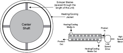
Figure 13.5: Scraped-wall heat exchanger
13.1.3.1 WET SYSTEMS—SINGLE PHASE (MISCIBLE) SYSTEMS
The science of mixing is far from complete. Designers of mixing equipment are not yet able to produce, from simple design principles, the optimum piece of equipment for a specific job even if they are given the necessary parameters and fundamental characteristics of the process and formula. One of the reasons for this is that the complete mathematical description of the flow pattern of fluid within each mixing vessel is extremely complex and difficult to achieve. Progress, however, is being made using the mathematical tools of dimensional analysis and modeling [4, 5, 6, and 7]. As an illustration of the practical usefulness of the data that can emerge from this analytical approach, a brief description of the relationship between some of the relevant parameters follows.
a. Flow Patterns: Fluids with Low or Medium Viscosity (< 5,000 centipoise)
Flow patterns in agitated vessels can be resolved into three principal types: tangential flow, radial flow, and axial flow.
In tangential flow, the liquid moves parallel to the direction of the impeller. Movement of liquid into the surroundings is small and there is little movement perpendicular to the blades except in eddies near the tips. Tangential flow may be observed in paddle mixers operating at low speeds or in liquids of sufficient viscosity to prevent centrifugal flow from being developed, Figure 13.6a.
During radial flow, the liquid is discharged outwards from the impeller by centrifugal force. If the moving liquid strikes the wall of the vessel, it splits into two sections, circulating back towards the impeller where it is re-entrained. The splitting of the flow at the wall induces further turbulence and mixing. There is usually some element of radial flow in all stirred vessels, but flat-blade turbines and disks with radial paddle blades or teeth are specifically designed to produce flow patterns that are primarily radial, Figure 13.6b.
Axial flow, as the name implies, takes place parallel to the axis of rotation. Usually the impeller or propeller blades are pitched so that liquid is discharged axially—the direction of flow may be from top to bottom of the vessel or vice versa, Figure 13.6c. Generally speaking the most difficult flow pattern to maintain is one of axial flow.
By far the most common form of mixing in liquids of low or medium viscosity (< 5,000 centipoise) is achieved by forced convection in stirred vessels. The motion of the liquid produced in the vessel must be sufficiently intense to sustain turbulence. Since it is unlikely that turbulence can be generated uniformly throughout the whole content of the vessel on the production scale, the liquid must be circulated continuously around the vessel so that all of it passes through those regions where turbulence develops. Thus, the number of important basic mixing parameters to be considered is two: the extent of turbulence, and the circulation rate of the contents.
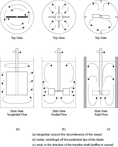
Figure 13.6: Flow patterns with different agitators
Viscous liquids showing shear-thinning characteristics present considerable problems to the cosmetics processor. The fluid close to the rotating impeller of a mixer is sheared at a high rate and so becomes relatively mobile. But as this is pumped away from the impeller, regions of less intense flow and hence of much higher viscosity are encountered. Turbulence is rapidly damped out, decreasing the turnover in the vessel and slowing down the mixing process. Scraper blades are often included on an anchor sweep, or contra-sweep to ensure good agitation along the vessel walls as the batch viscosity increases during cooling.
b. Impellers for Liquids of Low and Medium Viscosity
Paddle mixers produce mainly tangential flow and are usually mounted centrally because of their large diameter compared with that of the tank. For viscous liquids, the paddle is often of an anchor design equipped with scraper blades that remove product from the walls of the vessel.
Marine type Propeller mixers, Figure 13.7a, are restricted to use with low-viscosity fluids, since their pumping capacity becomes localized at viscosities above 5000 centipoise. They have pitched blades whose angle varies along the length from center to tip. Flow patterns developed by propeller mixers have a high axial component and the rate of circulation around the vessel is high. Though the ideal impeller diameter to tank diameter ratio (D/T) is 0.33 ± 0.05, propeller mixers are usually of relatively small diameter, typically three-bladed, and are used at speeds between 150 to 2500 RPM. Such stirrers are used extensively in the cosmetics industry for simple blending operations. Alternate propeller mixer designs are available. These are commonly called axial flow impellers.
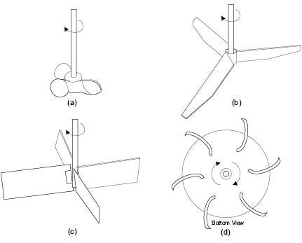
Figure 13.7: Designs of turbine impeller
Many portable mixers are of the propeller type. If the mixer is mounted centrally in the mixing tank, Figure 13.8 a, the surface becomes depressed and a vortex is formed. This is because of the natural movement of liquid to be drawn from above the impeller and towards its center. Generally, vortices are to be avoided because of the low order of turbulence and likely air-entrapment. Thus, propeller mixers should be mounted eccentrically, that is, offset from the center of the vessel at an angle other than perpendicular to the batch surface, Figure 13.8 b. Offset propeller mounting improves mixing efficiency by eliminating vortices, increasing turbulence, and improving batch turnover in the vessel. If the mixer must be mounted centrally, an alternate method of minimizing the formation of a vortex is through the addition of baffles, Figure 13.8 c. The baffles are normally equally spaced (e.g., four at 90° separations) and fixed to the vessel walls for efficiency. To improve ease of cleaning of the vessel, the baffles may not be fixed, but they then will not be sized the same to maintain the flow pattern required.
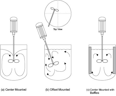
Figure 13.8: Portable mixer positioning
A turbine prop is a common impeller type used in cosmetics processing since it can cope with a wide range of viscosity and density. For liquids of low-viscosity, the flat-blade, axial-flow impeller is sometimes used, Figure 13.7 b. Slightly more viscous fluids are more efficiently mixed using the axial-flow flat-blade turbine shown in Figure 13.7 c. For very viscous materials, multiple radial-flow turbine blades, curved backwards in the direction opposite to the rotation, may be used, Figure 13.7 d. These require a lower starting torque and seem to give better energy transfer from impeller to liquid. Turbines produce a large flow of liquid with minimal shear and horsepower. They are normally mounted perpendicular to the top of the vessel with three or four baffles attached to the vertical vessel wall to reduce tangential and radial flow. Baffles help to induce and control the flow in both axial and radial directions. Used without baffles, the axial component generated by turbines remains secondary to the radial flow component, and the turbine does not efficiently turn over the entire batch. Typically, impellers of this kind are used at rotational speeds of 100 to 2000 revolutions per minute (RPM) as compared to the low speeds of 15 to 50 RPM for paddles.
Power consumption is of great relevance to the economics of the mixing process. The choice of the wrong equipment can lead to the consumption of vastly greater quantities of power than are necessary to achieve the desired end result. On the other hand, sufficient power must be available and applied to the fluid to ensure that the endpoint of the mixing process can be achieved in a sensible time [5, 6, and 7].
As can be seen in Equation 13.6, a change in impeller diameter has a more significant effect on the power required than a change in impeller speed. This is emphasized in the design of most drop-in homogenizers through their small head design powered by a large drive motor.
P  N3 D5
N3 D5
Where: P = Power in watts
N = Impeller Speed in revolutions per minute
D = Impeller Diameter in meters
Equation 13.6 Power relationship to impeller speed and diameter
d. Pumping Capacity and Velocity Head
Perhaps the most powerful concept to arise from the analytical approach to mixing concerns the way that power provided by each type of impeller is actually transmitted to the fluid. This relationship can be expressed generally as
P  Q H
Q H
Where: P = Power in watts
Q = Pumping Capacity in liters per minute
H = Velocity Head in meters
Equation 13.7 Power relationship to pumping capacity and velocity head
Q is the pumping capacity of the impeller (the volume of fluid displaced directly by the impeller in liters per minute) and H is the velocity head—this is related to the shear rate experienced by fluid leaving the impeller. A large slow-moving impeller might produce, for example, a large pumping capacity and a low-velocity head, while a small impeller operating at high speed might produce a lower volume of fluid pumping but at a much higher-velocity head. Most cosmetics production processes require high pumping capacity, while others require high shear rate. It is useful to know the parameters that affect both these functions and how they interrelate.
For simple blending operations (the manufacture of shampoos or colognes, for example) pumping capacity of the impeller is often of the greatest significance. Under conditions of laminar flow, the number of complete changes of the bulk (batch turnover) required to bring about homogeneity is approximately three. For a turbine operating in turbulent conditions, this is reduced to about 1.5. However, given that only a fixed amount of power is available from the motor, it is not likely that a relatively small turbine will have sufficient pumping capacity to push a fairly viscous product around by even this amount. Not surprisingly, the factor that determines whether power is used as pumping capacity or velocity head is the ratio of impeller to tank diameter (D/T).
Examining the relationship between power consumption and D/T ratio for equal process results in a given vessel completes the picture, Figure 13.9. The use of a D/T ratio larger than 0.6 lowers the power required to achieve the same end result. At the same time, this implies the use of lower impeller speed, and this inevitably means that the torque required to drive the mixer increases dramatically [8]. The amount of torque that a given mixer is able to generate depends largely on its construction. It becomes a question of economics whether to invest in a more substantial (and expensive) mixer in order to reduce the power consumption needed to achieve a given mixture quality.
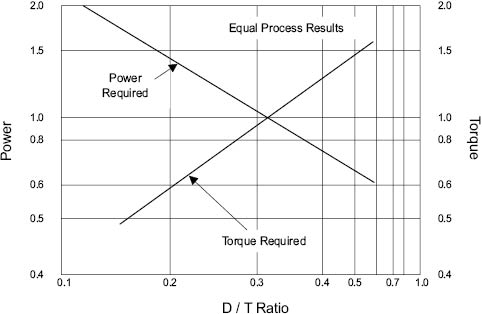
Figure 13.9 Power and torque relationship for equal process results [9]
Another important measurable parameter is mixing time, tm. This is the time taken to achieve the desired degree of homogeneity in the mixture. There are many methods by which this characteristic may be measured, but perhaps the most obvious is the time taken for a soluble dye to become uniformly dispersed throughout the mixing vessel (e.g., in the manufacture of a colored shampoo). The relationship between mixing time, tm, and the degree of uniformity can clearly be shown if some index of mixing level can be established.
A simple example of this would be the ratio of color intensity between the top and bottom of the vessel contents at intervals after dye is added to the top (so that uniformity is achieved as the mixing index, M, approaches unity). This comparatively simple experiment should give rise to a curve similar to that shown in Figure 13.10. Since the approach of M to unity is asymptotic, tm is difficult to measure accurately unless a colorimeter or other optical measuring device is available.
Once tm has been established, however, more useful insight into the parameters controlling mixing rates may be gleaned from relationships such as that illustrated in Figure 13.11 [5, 6, 7, and 10]. In Figure 13.11a (which relates to a viscous liquid in which turbulence is not established), tm, the mixing time, has been replaced by the product of rotational speed N and tm, that is, by the number of revolutions of the impeller. M, the mixing index, has been replaced by log (1-M) to present the plot in a linear fashion.
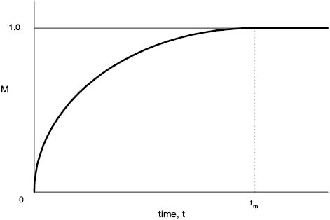
Figure 13.10 Mixing index, M, plotted against time to give mixing time, tm
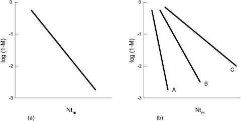
Figure 13.11: Mixing index, M, plotted against number of revolutions, Ntm
(a) Newtonian fluids (b) non-Newtonian fluids
It is interesting to note that for Newtonian fluids (ideal response between stress and strain) precisely the same plot is produced whatever the viscosity of the medium and speed of the impeller. In other words, only the number of impeller revolutions determines the change in mixing index. This is not true of non-Newtonian fluids—plots A, B, and C in Figure 13.11 b, which represents liquids showing increasing divergence from Newtonian behavior. This illustrates the difficulties of mixing non-Newtonian media in which flow is damped out rapidly by regions of high viscosity away from the vicinity of the impeller blade.
The ratio of tank dimensions can be an important factor in determining the efficiency of any mixing process. It is sensible to perform a simple blending, such as alcohol-water, in tall cylindrical vessels of small cross-section using a propeller or turbine mixer with two or three sets of blades located two to three blade diameters apart on the same shaft. This stirred tank setup allows the capability to make variable batch volumes with high axial flow. For low-viscosity lotions, a hemispherical kettle often replaces the dished bottom conical tank to maximize the batch turnover achieved with an offset-mounted propeller mixer. Normally the ratio of kettle diameter to kettle height is close to 1:1. In the production of an emulsion of medium viscosity, it is desirable to keep the height of the vessel between 1 and 1.5 times its diameter.
g. Flow Patterns: Fluids of High Viscosity
As the viscosity of the mixture increases, it becomes increasingly difficult—and eventually mechanically impossible—to produce turbulent flow within the mixing vessel. At viscosities of 100,000 centipoise or above, flow is inevitably laminar, power consumption high, and the rate of mixing exceedingly low. In such systems, the input power should be used to create disorder (mixing) but is used to create heat. The rate of temperature rise is dependent upon the energy input, the thermal conductivity of the mixture, and the efficiency of the cooling surfaces; but the range 1° to 3°C per minute would include many cosmetic mixing processes of this kind.
Generally it is difficult or impossible during industrial mixing of highly viscous materials to dissipate heat faster than it is generated. This is particularly true if the mixing vessel is of large capacity (in which the ratio of volume to heat-exchange surface is high) and if appreciable films of chilled liquid are allowed to build up on the walls of the vessel, so insulating the contents from further cooling. The increase in temperature associated with such processes has both advantages and disadvantages. On the one hand a rise in temperature might cause a decrease in viscosity, making mixing more efficient, and might also help in the melting or dissolution of some of the components of the mixture. Taken too far, on the other hand, the decrease in shear stress caused by the fall in viscosity can decrease the efficiency of stress-dependent processes. This can be seen when breaking up and dispersing pigment agglomerates. The increase in temperature may damage the product by causing the thermal degradation of heat-sensitive components such as actives, preservatives, and perfumes. The relatively high-energy input required while mixing viscous materials also influences the mechanical construction of the mixing machinery and the method by which mixing is achieved.
h. Impeller Types and Mixers for High-Viscosity Fluids
Propellers and turbines, as already mentioned, work best under turbulent conditions at relatively high rotational speeds. In viscous products (given that such speeds are attainable at all), flow is confined to the regions very close to the impeller. Large stagnant regions in the vessel exist where no mixing can occur without the employment of some secondary mechanism. To eliminate these stagnant regions large impellers such as paddles, gates, anchors, and leaf impellers may be used. These sweep a much greater proportion of the vessel and produce more extensive flow. Usually such impellers are designed to have close clearances with walls, giving a degree of wall scraping. This helps to eliminate buildup of unmixed materials at the walls, provides a region of high shear for dispersing aggregates and lumps, and may improve the wall heat transfer to and from the bulk.
Such impellers provide extensive flow but only of the tangential and radial variety. Axial flow, and therefore top-to-bottom mixing, is almost totally absent. This is a limitation of the design. Several suppliers have developed agitation techniques that include special baffles (often of variable pitch) that induce flow in both the downward and upward directions. For this reason, recycling the batch either externally through a pump or with time using the pitch of the sweep blade becomes an important consideration.
An alternative approach to the problem created by lack of flow in viscous media is the use of impellers that progressively sweep the whole contents of the vessel while the mixture remains stationary. Examples of this include the mixer in which a helical screw sweeps the wall of a conical mixing chamber, Figure 13.12. Equipment that exhibits a greater degree of distributive mixing may be utilized for more viscous products such as mascaras and toothpastes. Such mixers are designed to produce bulk flow and laminar shear by spatial redistribution of elements of the mixture. Perhaps the most commonly encountered mixers of this type are of the single or double action planetary type or the two-blade “dough” mixer. Their essential feature involves the cutting and folding of a volume of the mixture and the physical replacement of it into another part of the mixture where it is cut and folded again.
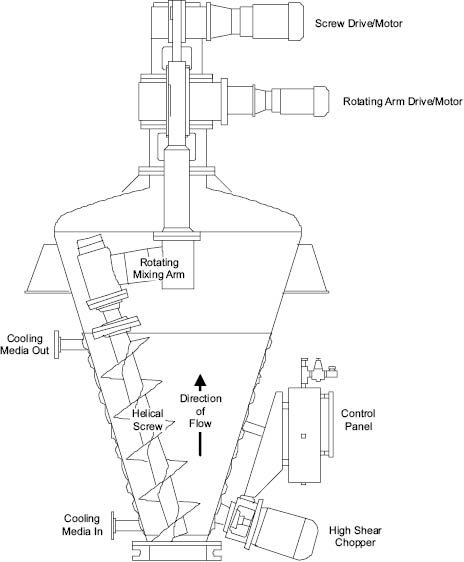
Figure 13.12: High solids blender [11]
Figure Courtesy of Charles Ross and Son Company, Hauppauge, New York
The static mixer is essentially an in-line mixing device in which mixtures flowing through a pipe are cut and folded by a series of helical elements in a circular tube, Figure 13.13. These elements (which do not move—hence the name “static”) turn the flowing mixture through an angle of 180°. Since alternate elements have opposite pitch and are displaced 90° to each other, this causes the bulk flow to reverse direction at each junction. The leading edge of each element becomes a cutting device, splitting and refolding the mixture in and on itself. This type of static mixer works well with thick materials. Other static, or motionless, mixer designs utilize the divergence and convergence of flows to induce mixing with some control as to the shear developed. This type of static mixer works well with thin materials. It can be seen that with both high and low viscosities, excellent mixing can be achieved in a relatively short length of pipe and with relatively few static elements. Each element splits the product stream in two and combines the two new streams with parts of the previously split streams. Other styles of static mixers are also available that offer specialty features such as adjustable gap settings and lower pressure drops.
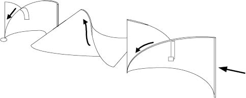
Figure 13.13: Static mixer elements
Finally, mention must be made of extruders, in which a helical screw forces the bulk mixture to flow down a tube. Here, the pressure generated can be enormous, as in soap plodding, and such energy can cause materials with high viscosity to undergo laminar flow and change structure. The actual flow pattern produced is complex, being a combination of pressure and drag flow within the tube [12].
13.1.3.2 WET SYSTEMS – MULTIPHASE SYSTEMS
Two major immiscible phases (referred to as “oil” and “water”) together with the emulsifier are brought together to form an emulsion. If the chemistry is favorable, very little energy is needed to produce a stable product. To minimize the level of emulsifier, it may be possible to use energy to force the emulsion to a stable endpoint.
The level of energy required will be formula dependent. Under turbulent conditions, one phase (usually the discontinuous or internal phase) is broken up into droplets (predominantly by the action of shear stress imparted by turbulent eddies). The droplets are distributed throughout the other phase (the continuous or external phase).
While the droplets remain larger than the majority of the flowing particles, they will continue to break up into ever-smaller droplets. Eventually a point is reached in this process when the available power creating the turbulence cannot provide the shear stress necessary to reduce the droplet size any further. At this stage an emulsion exists containing droplets of a certain mean diameter ranging from dmin to dmax. Provided that it is correctly chosen, the emulsifier prevents the rapid coalescence of these droplets, and a stable emulsion may be formed.
In order to obtain products of maximum stability that can be made consistently from batch to batch, it is generally desirable to keep the droplet size distribution as narrow as possible. In a CSTR, droplet size is smallest near the impeller in the region of greatest turbulence whereas the maximum droplet size is to be found in any quiescent region of the tank. Thus it can be seen that dmin is fixed by the power available to generate turbulence, and dmax depends on the efficiency of the mixing in the tank to produce a good circulation rate, to bring all the contents through the region of maximum turbulence. This will minimize the distribution range between dmin and dmax.
Superimposed on the effect of circulation patterns in the vessel is an additional factor affecting the particle size range of the droplets. For a given vessel and impeller the effect of increasing the mixer speed should be to reduce the particle size range to a minimum, after which a further increase in speed could give rise to instability and coalescence. In practice, coalescence does not take place if a sufficient quantity of emulsifier is present; nevertheless it is important to attain the correct impeller speed to reduce the particle size range to a minimum.
In any emulsion the orientation of the phases (that is, whether the oil or the water phase is continuous) is determined principally by the choice of emulsifier and the volume ratio of oil to water. Usually there is a range of volume ratios over which either phase may be dispersed, depending upon the method of manufacture.
Initially, only one phase is present in the mixing vessel containing the impeller. The second phase will form the dispersed or discontinuous phase upon its addition. If the second phase is combined with the choice of emulsifier, which eventually leads to a volume ratio at which the system is more stable with the second phase being continuous, then the emulsion will spontaneously invert and the continuous and discontinuous phases will switch. When an inversion takes place, it is very often accompanied by an abrupt change in droplet size. Where this droplet size change is a decrease, the inversion leads to a more stable emulsion and gives rise to a valuable method of manufacture. This inversion process is often an effective method of producing a uniform, fine droplet size and may improve stability of the emulsion. Chemical formula, processing temperature, and energy must all combine at the correct levels for an inversion process to be reproducible in both the Laboratory and Production. Available energy level in Production is usually the limiting factor.
In a batch manufacturing process for emulsions, there are four possible methods of adding the emulsifier:
- • dissolving or dispersing an emulsifying agent in water
- • dissolving or dispersing an emulsifying agent in oil
- • dissolving or dispersing an emulsifying agent in both the water and oil
- • adding the water and oil phases alternately to an emulsifying agent
Normally, the emulsion process starts with a water phase to which the oil is added. An oil-in-water emulsion is initially produced, but an inversion to a water-in-oil emulsion may take place if sufficient oil is added. If the emulsifier is added to the oil phase, this mixture may be added directly to water to form an oil-in-water emulsion; if the water is added to the surfactant/oil mixture, a water-in-oil emulsion is formed initially.
Some emulsions are stabilized by “soaps,” which are formed at the interface between the two phases. In this case, the fatty acid is dissolved in the oil and the alkaline component is dissolved in the water. The two phases can be brought together in any order. The neutralization reaction, which forms the emulsifier, takes place as the phases are combined.
A less-used method is one in which both the water and oil phases are added alternately to the emulsifying agent. Usually, the small improvement in product quality obtained by the use of this method does not warrant the complication it causes in the manufacturing procedure.
The primary reason for operating above room temperature during the manufacture of an emulsion is to ensure that both phases are in the liquid state. In particular, the oil phase may contain fats and waxes that are solid at room temperature. The water phase is customarily heated slightly above the temperature chosen for the oil phase so as not to cause any sudden solidification upon blending. There is, however, an interesting variation: emulsification between a hot oil phase and a cold (usually room temperature) water phase. An illustration of this procedure in which mixing and homogenization of the phases take place simultaneously is shown in Figure 13.14. The advantage of such a method is the saving of time and energy by not having to heat the aqueous phase and by reducing the time and energy required to cool the product to room temperature.
A secondary reason for heating a phase is to minimize microbiological concerns associated with a raw material. Preservatives are normally added to a formula to control any issues produced by the consumer. Minimizing growth can be performed in the process by using high-energy homogenizers (an inefficient use of the equipment) or by phase temperature (holding the phase at an elevated temperature for an extended period of time). A challenge when looking to move from a hot water/hot oil process to a cold water/hot oil process is whether or not the microbiology team supports the process change. It does not help to make batches quickly if they fail microbiological testing.
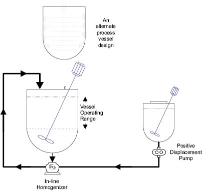
Figure 13.14: Hot/cold processing emulsion system
e. Emulsion Processing Equipment – Mixing
Related posts:


Stay updated, free articles. Join our Telegram channel

Full access? Get Clinical Tree


