2
Clinical Biomechanics of the Pediatric Craniocervical Junction and Subaxial Spine
Spinal biomechanics is the study of the consequences of external physiological or pathological forces applied to the spinal column.1 The most important clinical concept regarding the biomechanics of the spine is that of stability. According to White and Panjabi,2 instability is defined as the “loss of the ability of the spine under physiologic loads to maintain its pattern of displacement so that there is no initial or additional neurological deficit, no major deformity, and no incapacitating pain.” This definition allows the clinician to make interpretations based on the initial injury as well as the known natural history of certain injuries and conditions. This definition also allows certain spinal deformities to be considered stable as long as they do not lead to neurological insult or incapacitating pain. The body of knowledge used to classify injuries as stable or unstable is gathered by anatomical studies, radiographic studies, and mechanical loading experiments on cadavers.
Most of the studies of biomechanics of the cervical spine have focused on adults. Conceptual simplifications with models such as the two-column and three-column spine are created to make predictions as to whether a specific injury pattern is unstable.3–6 Although pediatric cadavers are rare, it is clear from clinical experience that the pediatric spine is not a scaled down adult spine and has unique biomechanical considerations with different patterns of injuries and different criteria for spinal instability. Furthermore, the unique and complex articulations of the craniocervical junction render modeling extremely difficult. Models created for the subaxial spine do not apply to the craniocervical junction. Many assumptions about the biomechanics of the pediatric craniocervical junction are, therefore, derived from clinical data and extrapolated biomechanical studies from the adult spine. Criteria for clinical instability have relied on a host of radiographic measurements of the various bony landmarks in the occipitoatlantoaxial (O–C2) complex. This chapter reviews the anatomy of the craniocervical junction and discusses the elements involved in maintaining the stability of the O–C2 complex. Also reviewed are the anatomy of the subaxial spine and the elements involved in maintaining stability of the subaxial spine.
 Review of Normal Biomechanics
Craniocervical Junction: Normal Kinematics
The biomechanical unit of the craniocervical junction is the occipitoatlantoaxial (O–C2) complex. The occipitoatlantal (O–C1) joint and the atlantoaxial (C1–C2) joint of the O–C2 complex function together as a single unit that controls the movement of the head in relation to the spine. Within this unit, the atlas (C1) serves as a wedged washer between two spheres of mobility (Fig. 2–1). The articulation between the occipital condyles and the atlas is cup shaped in the sagittal plane and medially tilted in the coronal plane. This orientation allows up to 20 degrees of flexion/extension and 8 degrees of lateral bending.2 Flexion and extension at O–C1 is ultimately limited by the contact of the rim of the cup-shaped atlas against the base of the skull.7 Lateral rotation beyond 8 degrees is restrained by the physiological separation limit of the contralateral O–C1 joint. Rotation at the O–C1 joint is largely blocked by the oblique bony alignment of the articulation. Whereas classic cadaver studies have shown an absence of rotation between the occiput and C1, more recent in vivo studies have shown up to 4 degrees of axial rotation to one side between O and C1.8,9 In contrast, the biconvex cartilage articulating surface and laterally tilted facet orientation between the atlas and axis allow a large degree of rotation centered about the dens. Up to 60% of the axial rotation of the entire cervical spine occurs at C1–C2, with a described range of 32.2 to 47 degrees to one side.10–12 Kinking and stretching of the vertebral artery have been described at the transverse foramina after 30 degrees of rotation at the ipsilateral artery and after 45 degrees of rotation at the contralateral artery.13,14 Sagittal movement of the arch of the atlas along the slightly dorsally curved dens provides additional flexion and extension of 20 degrees at C1–C2. Very little lateral bending occurs at C1–C2.
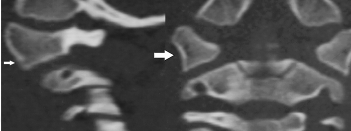
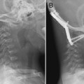
Figure 2–1 (A) Sagittal reconstruction of a computed tomographic (CT) image of C1 through its lateral mass in a normal child. The arrow is pointing to the lateral mass of C1. (B) Coronal reconstruction of a CT scan of C1 in the same patient. The arrow is pointing to the lateral mass of C1.
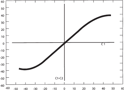
Figure 2–2 Normal motion curve of C1 and C2 rotation (Adapted from Pang D, Sun PP. Pediatric vertebral column and spinal cord injuries. In: Youmans JR, ed. Neurological Surgery. Philadelphia: WB Saunders; 2004:3515–3557).
The dynamics of axial rotation can be described by a motion curve where the degrees of rotation are plotted on an x- and y-axis (Fig. 2–2). Because there is minimal rotation at O–C1, the head essentially moves with C1 during rotation, and the degree of head axial rotation is essentially the same as the degree of C1 rotation. This is plotted on the x-axis. The degree of rotation between C1 and C2 is plotted on the y–axis. In vivo data on the motion of C1 on C2 has been obtained by computed tomography (CT) and magnetic resonance imaging (MRI).8,10 The motion curve starts off linear for the first 20 to 30 degrees of rotation because C1 initially moves entirely independently of C2 and the degree of rotation of the C1 is the same as the degree of rotation between C1 and C2. This means that the initial phase of head rotation—the first 20 to 30 degrees—occurs at the C1–C2 joint. As the articular joint capsules and alar ligaments become taut, C2 begins to follow C1 in rotation, and the motion curve flattens out until the limit of the range of motion is reached between C1 and C2. Subsequent head turning is then allowed by subaxial rotation.
Axial rotation is coupled with motions in other axes in the O–C2 unit. Maximal axial rotation is coupled with 1.7 to 4.9 degrees of lateral bending to the opposite direction at O–C1 and 3 degrees of lateral bending to the opposite direction at C1–C2.12 Rotation is also coupled to extension: up to 13 degrees at the O–C1 joint and 6 degrees at the C1–C2 joint. Downward translation between C1 and C2 is also seen with rotation, presumably from the biconvexity of the articulations.
Subaxial Cervical Spine: Normal Kinematics
The stability of the subaxial spine (C2–C7) depends on the ability of the vertebral column and intervertebral disks to withstand compressive forces and on the ability of the ligaments connecting these elements to allow for normal motion while resisting forces that would lead to pathological deformity. The intrinsic biomechanical properties of the vertebral bodies and geometric considerations are important in determining the ability of the subaxial cervical spine to withstand physiological stressors.
In this region of the spine, the vertebral bodies are aligned directly above one another, separated by intervertebral disks. The opposing surfaces of the vertebral bodies are gently curved in the sagittal plane. Between any two bodies, the anterior-inferior border of the upper body hangs downward toward the anterior-superior surface edge of the vertebra below. The superior surface slopes downward and forward. This shape is conducive to the flexion–extension motion that occurs at this joint. In the adult, the total range of flexion and extension is 60 to 75 degrees. The greatest motion of flexion and extension is at the O–C1 junction (13 degrees), and the next greatest is between C5 and C7. Dynamic radiographs in children show that the upper cervical segments in infants and children are hypermobile in flexion. The fulcrum for maximal flexion is at C2–C3 in infants and young children, at C3–C4 in children ages 5 or 6 years, and at C5–C6 in adolescents and young adults.14–16 The predilection for C2 and C3 forward displacement occurs because the joint is more mobile in children given that the articular facets of C2 and C3 lie in a relatively horizontal plane allowing for forward displacement. The more caudal cervical facets are more vertical, such that subluxation would require more force.16
The vertebral bodies in the subaxial cervical spine are also curved from side to side. The inferior surface of the upper vertebral body is slightly convex posteriorly, and this convexity is received by a concavity of the body below and by its uncinate process. This shape promotes a side-to-side rocking motion.7 In adults, the facets are directly opposed to each other, and the mature uncinate processes provide additional support and prevent lateral and rotational movements.7 In children, however, the facet joints are more horizontally oriented and provide less resistance to rocking and translation between vertebrae. In addition, the uncinate processes are absent in children under the age of 10 years.16,17 The overall orientation and shape of the vertebral bodies in children allow more motion to physiological loads.
The intervertebral disks are located between vertebral bodies and must respond to a variety of load vectors during physiological and traumatic load, including compression, bending, and tension.18 The intervertebral disks consist of an anteriorly well-developed and thick anulus that tapers laterally and posteriorly. There is no true anulus posteriorly, only a few fibers near the median plane. The thick anterior anulus acts as an interosseus ligament and resists extensions. The nucleus pulposus at birth has a water content of 88% and contributes to the general malleability of the cervical spine. In loading of the cervical spine, the intervertebral disks carry over 60% of the compressive loads.19
Determinants of Stability at the Craniocervical Junction
Stability at the craniocervical junction level is achieved by three structures that provide major elements of support and two structures that provide minor support. The major supporting structures are the cup-shaped joints at the craniocervical articulation, the capsular ligaments, and the tectorial membrane.20 At the C1–C2 joint, two major structures provide stability.21 These structures are the odontoid process and the transverse ligament. They provide the majority of stability at the C1–C2 joint, and their integrity is critical. The transverse ligament is a thick horizontal band of the cruciate ligament that attaches to the inner aspect of the C1 ring, and straps hold the dens against the anterior arch of C1. It is the pivotal stabilizer against horizontal translation of the dens into the spinal canal. In adults, the ligament is 7 to 8 mm thick and can withstand 350 N of force.22 The strength of the transverse ligament is clinically illustrated by the occurrence of dens fractures in adults and synchondrosis failure in young children while the ligament itself remains intact.
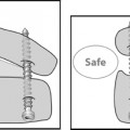
Although the transverse ligament holds the C1 ring against the dens, a unique aspect of the O–C2 region is that, unlike the remainder of the spine, stability is otherwise not primarily provided by the segmental structures (Fig. 2–3). The loose articular capsules and thin atlantoaxial and occipitoatlantal membranes between the occiput and C1 and between C1 and C2 allow an extensive range of motion but are not the dominant stabilizers.2 In addition, there is no correlate of the segmental interspinous ligament in the O–C2 region. The posterior interspace between O–C1 and C1–C2 is filled with suboccipital musculature that is attached to the underlying posterior occipitoatlantal and atlantoaxial membrane dural complex. These small and delicate muscles are theorized to have proprioceptive functions but are unlikely to limit motion.23
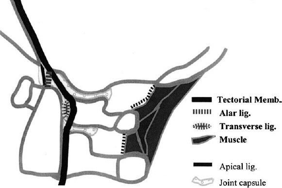
Figure 2–3 Ligaments of the craniocervical junction. This panel schematically shows the normal ligaments of the craniocervical junction.
The stability in the O–C2 region is largely provided by the internal ligaments and muscles directly between the occiput and C2. Among the internal ligaments, the tectorial membrane and alar ligaments are especially important, as demonstrated by Werne in a series of cadaver studies.24 The tectorial membrane is a well-developed continuation of the posterior longitudinal ligament (PLL) that holds the body of C2 firmly to the clivus and the anterior rim of the foramen magnum. Initial flexion in the occipitoatlantoaxial unit is limited by skeletal contact between the basion and dens. Additional flexion moves the basion forward and downward over the dens. The tectorial membrane limits this movement by draping and stretching over the dens between the basion and the body of the axis. Extension is also checked by the tectorial membrane and by bony contact between the opisthion and the arch of C1. Lateral bending and rotation are controlled by the alar ligaments, which span obliquely from the posterolateral surface of the dens, attach partly to C2, and then attach to the medial occipital condyles. Sectioning of the tectorial membrane alone results in increased range of flexion and extension as well as vertical translation beyond the normal range between the dens and cranium. Removal of the alar ligaments results in increased contralateral bending and rotation. When both the alar ligaments and tectorial membrane are cut, frank occipital subluxation results. In vivo clinical MRI data in children also demonstrate that involvement of the tectorial membrane in O–C2 injuries is a critical threshold for instability. Although there is a spectrum of various traumatic abnormalities of O–C2 ligamentous and muscular structures, clinical manifestations of instability such as spinal cord injury, radiographic dislocation, and posttraumatic deformity occurred only when the tectorial membrane is involved.25 The remainder of the occipital-–axial connections, namely, the ascending band of cruciate ligament and the apical ligament, are too delicate to limit motion. In fact, the apical ligament has been shown to be a vestigial structure that offers no stability and is absent in 20% of cadavers studied.26
Muscular action and bony contact also contribute to the stability of the O–C2 unit. In vitro studies in which the muscles have been removed revealed that the O–C1–C2 complex has a much larger neutral zone than the subaxial spine and that a much smaller load is needed to create a large displacement.27 The frequent involvement of the muscles in an isolated injury or in consistent association with other ligamentous disruptions in the O–C2 region supports the idea that they also provide considerable stabilization in the craniocervical region.25 Hence, muscular action is thought to be substantially responsible for holding the cranium firmly to the spine.
Determinants of Stability of the Subaxial Cervical Spine
Related posts:
 Advanced Occipitocervical Surgery in Children
 Common Pathological Conditions of the Pediatric Craniovertebral Junction and Cervical Spine
 Advanced Atlantoaxial Surgery in Children
Stay updated, free articles. Join our Telegram channel

Full access? Get Clinical Tree


