8 Computer Imaging for Facial Plastic Surgery
Introduction
Computer imaging in clinical practice has changed enormously since its introduction in the 1980s. Enhanced technologies in computer hardware and software, combined with extensive public information about facial surgery, have increased the popularity and availability of imaging systems in surgeons’ offices. Imaging systems have been used for diverse purposes such as resident and fellow education, 1 patient–surgeon communication, 2 detailed facial analysis, 3 archiving of patient images, and marketing of surgical practices. 4 Now, with the advent of threedimensional (3D) cameras, 3D techniques are being used to capture facial topography and assist in the planning and analysis of complex facial reconstructions. 5 There are many practical, ethical, and legal issues that have been raised by the advent of computer imaging. This chapter highlights this interesting tool in facial plastic surgery.
Historical Background
The earliest forms of patient imaging involved freehand sketches of anticipated surgical results by surgeons. Photographic techniques were not practical or affordable until the second half of the 19th century. As emulsion photography became more available, alterations of these images were used to communicate changes to the patient. Patient images in profile against dark backgrounds could be used to demonstrate reduction rhinoplasty or rhytidectomy procedures. In the 20th century it became possible to print photographs on paper, and this made the foregoing techniques more practical. Drawing on the back of photographic prints against background light or projecting 35 mm slides onto a white drawing tablet could be used to envision profile changes. Instant photography provided another tool for swiftly demonstrating patient characteristics and could be drawn upon to suggest changes.
However, when computer imaging became available, the relative ease and speed of the computer overshadowed all of these time-tested methods. Although the early computer graphic programs were cumbersome and required practice, the newer systems are much more user-friendly. In addition, the price of computer hardware, imaging software, and digital photography equipment continue to decline even as the technology rapidly improves, making computer imaging accessible to many, if not most, facial plastic and plastic surgeons. One must remember though, the common element in any imaging system is that surgeons must have a clear idea of what they would like their patients to see and understand. This requires that the surgeon have a well-developed sense of facial analysis and aesthetics, and the ability to express this with the computer tools available.
System Requirements
Modern imaging systems may be purchased from various vendors with a variety of features. The core of each system involves an image capture device, such as a digital video, digital still, or 3D camera. Digital cameras are now commercially available with up to 32 megapixels per image. A camera with at least an 8 megapixel capacity will serve very well for most imaging techniques, but most cameras on the market today far surpass this number of megapixels. The image is then downloaded to a computer from a memory card or directly in a tethered mode, then archived for current or future use. Each imaging system utilizes special software developed for patient image modification. Graphics boards, digital drawing tablet, large hard drive, backup tape system, monitor, and lighting system are essential. The computer should include at least 2 gigabytes of RAM, but more might be required for the newer operating platforms, at least 200 gigabytes of hard drive space, and a central processing unit of at least 4.0 MHz speed to cope with the large memory and speed demands of graphic imaging. It is also strongly recommended that images be backed up onto a remote, protected server. The equipment should be situated so that patient and surgeon may sit near the monitor and discuss proposed surgical techniques and anticipated changes. Many offices combine the lighting used for traditional photography and computer imaging in one multimedia room. A printer may be used to make hard copies of computer images if desired.
Many commercial systems are available for purchase in a wide range of prices. Those systems with 3D digital image capture systems and sophisticated hardware can run as high as $30,000. Basic 2D systems can cost a fraction of this. It is possible to assemble reasonable hardware and purchase software to reproduce these graphic systems for a much lower cost. This requires the ability to integrate computer software and hardware into a working unit.
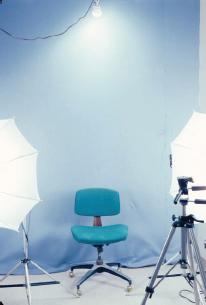
The patient background should be a consistent color and shade to facilitate a fair comparison of images. A light blue background seems to be aesthetically pleasing and provides good contrast with natural skin tones. 6 Lighting should be provided that eliminates shadows but does not flatten out the details of the face and skin. Indirect modeling lights with umbrellas and diffusers from at least two directions will provide excellent images ( Fig. 8.1 ). Darker backgrounds such as black or brown provide sharper contrast, but tend to flatten the images and hurt the flesh tones.
Images are captured in the same patient positions as with conventional photography. Soft tissue reference points, such as the tragus, angle of mandible, and anterior hairline, should be visible to enhance analysis potential. It is recommended that all images be stored on the hard disk and if possible, remote server, prior to initiating graphic changes. This will prevent loss of images if there is a computer failure. At the minimum, each system should have an external backup, such as a portable hard drive or remote server, to download files at the end of each day. Often, back up to a remote server can occur in real time depending on how one sets up the directory for the database software.
In 1998 it was estimated that 8 to 10% of cosmetic surgery practices were utilizing computer imaging in some capacity. 7 A 2006 survey of the American Academy of Facial Plastic Surgery members showed that almost 90% of surgeons are utilizing digital photography to capture pre- and postoperative patient images and almost twothirds of academy members are utilizing some form of photo-imaging software for preoperative consultations. 8 These numbers are continuing to increase.
Analysis and Applications
Computer imaging provides an opportunity to assess patient characteristics in a quantitative fashion. These analytical data can be used in conjunction with aesthetic judgment to plan potential facial surgery. Imaging also gives the patient a chance to assess the surgeon’s goals, thus creating a very important communication device that was lacking before sophisticated imaging systems were available. The surgeon may also assess whether the patient has realistic ideas of what facial surgery can attain. Based on this interaction either patient or surgeon may decide that surgery is not indicated due to patient–surgeon incompatibility. This is beneficial for surgeon and patient alike.
In planning facial surgery the relationship to quantitative facial ideals may be considered. With the imaging systems it is fairly easy to generate data based on quantitative facial measurements as defined by several authors to assist in facial analysis. 9 , 10 , 11 , 12 These techniques have been used for instruction in facial analysis for resident surgeons and fellows. The most common key points for facial analysis, definitions, and aesthetic norms are listed in the glossary and Tables 8.1 and 8.2 .
Frankfort and vertical planes | 80–95 degrees |
Aesthetic triangle |
|
Nasofrontal angle | 115–130 degrees |
Nasofacial angle | 30–40 degrees |
Nasomental angle | 120–132 degrees |
Mentocervical angle | 80–95 degrees |
Anterior facial height |
|
Nasal height ratio | 47% |
Lower facial height ratio | 53% |
Legan facial convexity angle | 8–16 degrees |
Nasolabial angle | 90–120 degrees |
Columellar show | 3–5 mm |
Goode nasal projection ratio | 0.55–0.60 |
Alar lobule ratio | 1:1 |
Vertical lip ratio | 1:2 |
Mentolabial sulcus | 4 mm |
Frontal analysis |
|
Facial height |
|
Nasal height ratio | 47% |
Lower facial height ratio | 53% |
Nasal width | Equal to intercanthal distance |
Intercanthal distance | 25.5–37.5 female; 26.5–38.7 male |
Rhinoplasty and Mentoplasty
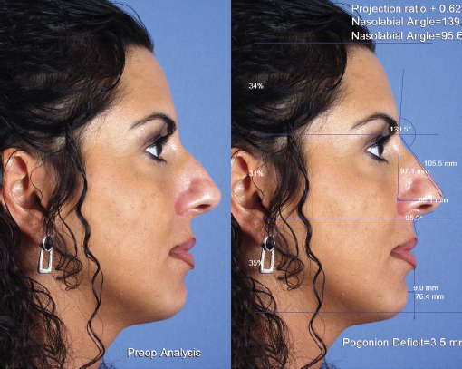
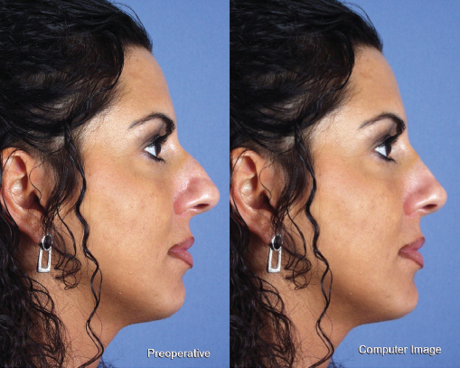
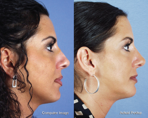
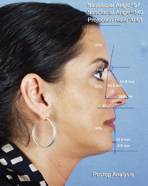
As an example of quantitative analysis using the computer imaging system, consider the case of a 30-year-old woman with a complaint of nasal deformity and retrognathia. The preoperative computer analysis is shown in Fig. 8.2 . The measurement indicates that the nasal tip projection is adequate, and the measurements also indicate poor chin projection. All other parameters were within normal range. A computergenerated revision is shown and compared with the preoperative image in Fig. 8.3 . The patient elected to undergo septorhinoplasty and mentoplasty. The postoperative profile is compared with the computergenerated image in Fig. 8.4 . The postoperative analysis is shown in Fig. 8.5 , with all measurements now in the normal range. It is also important to use aesthetic sense to judge if the results are pleasing to the eye as well as statistically correct.
Related posts:


Stay updated, free articles. Join our Telegram channel

Full access? Get Clinical Tree


