CHAPTER 51 Surgical Options for Acetabular Reconstruction
Custom Components
Current treatment options for massive acetabular defects encountered in revision total hip arthroplasty (THA) are numerous but often associated with inconsistent clinical results and substantial complication rates. These reconstructive options include creation of a high hip center with a standard acetabular component, jumbo hemispherical acetabular components, bipolar hemiarthroplasty, acetabular impaction bone grafting combined with a hemispherical cup, massive structural allografts, oblong acetabular components, modular trabecular metal cups with augments1,2 and noncustom acetabular reconstruction rings.3 Difficulties associated with these methods in patients with massive periacetabular bone loss have included loss of fixation, component fracture, hip instability, and gait alterations caused by failure to restore functional hip biomechanics.
INDICATIONS
Patients may incur massive periacetabular bone loss for a variety of reasons. The most common cause is periprosthetic osteolysis secondary to excessive PE wear requiring revision surgery. Two classification systems exist for evaluating periacetabular bone loss. These classifications are based on the severity of bone loss and ability to obtain implant fixation. Generally, previously mentioned means of acetabular reconstruction other than CTACs are appropriate for Paprosky classes I to IIIA and American Academy of Orthopaedic Surgeons (AAOS) classes I and II, whereas Paprosky type IIIB and AAOS type III and IV defects are well suited for CTAC implantation. In the two largest existing series, patients who were considered to have Paprosky type IIIB or AAOS type III or IV periacetabular bone loss were selected for CTAC reconstruction.3,4
THE IMPLANT
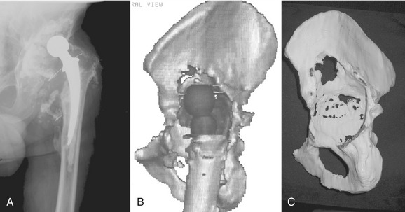
A standard CT scan of the pelvis with or without implants in place with 3-mm cuts from the anterior superior iliac spine to the obturator foramen and 5-mm cuts for the remainder of the pelvis is obtained. The uncompressed data are then recorded on a CD-ROM and sent to the implant manufacturer. The manufacturer (Biomet or DePuy, Warsaw, IN) will provide detailed instructions on surgeon request. Metal subtraction software is used to create a three-dimensional, one-to-one model of the hemipelvis for the surgeon to analyze (Fig. 51-1). The engineers rely on markings of the flanges made on the pelvic model by the surgeon, and a clay prototype of the component is subsequently prepared. The head center location is chosen based on patient-specific considerations, including leg length discrepancy, planned retention or revision of the femoral component, length of contralateral leg, and size of the current acetabular component and should be specified in the initial order. Generally, the vertical head center location is established by first determining the approximate anatomic position of the head center using the superior aspect of the obturator foramen as a reference point. The remaining bone of the anterior and posterior columns determines the head center in the coronal plane, whereas the flange geometry and component face diameter guide the position of the head center in the sagittal plane. The component face orientation is established by setting the abduction and anteversion angles of the cup. The abduction angle is established using the plane of the obturator foramen as a reference. The anteversion angle is established using the plane of the iliac wing and the obturator foramen as references.
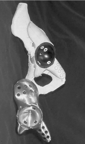
The iliac and ischial flanges contain multiple rows of screw holes for 6.5-mm screws. Five or six screw holes in the ischial flange are preferred because this area has proven to be the most common site of fixation loss. Two rows of three or four screw holes have proven sufficient for fixation of the iliac flange (Fig. 51-2). The pubic flange is smaller in size and contains no screw holes.
OPERATIVE TECHNIQUE
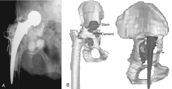
The CTAC is best implanted through an extensile posterolateral approach with or without a trochanteric osteotomy. Care must be taken to protect the superior gluteal artery and nerve when the gluteus minimus and medius are elevated from the iliac wing. In patients with severe acetabular component protrusion, a retroperitoneal approach initially may be required to carefully free the iliac vasculature from the protruded acetabular component, followed by revision THA through a separate extensile posterolateral or transtrochanteric surgical approach (Fig. 51-3). The sciatic nerve is protected by extending the hip when the hamstring origin is cleared from the ischial tuberosity.


Stay updated, free articles. Join our Telegram channel

Full access? Get Clinical Tree


