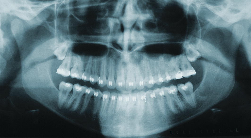
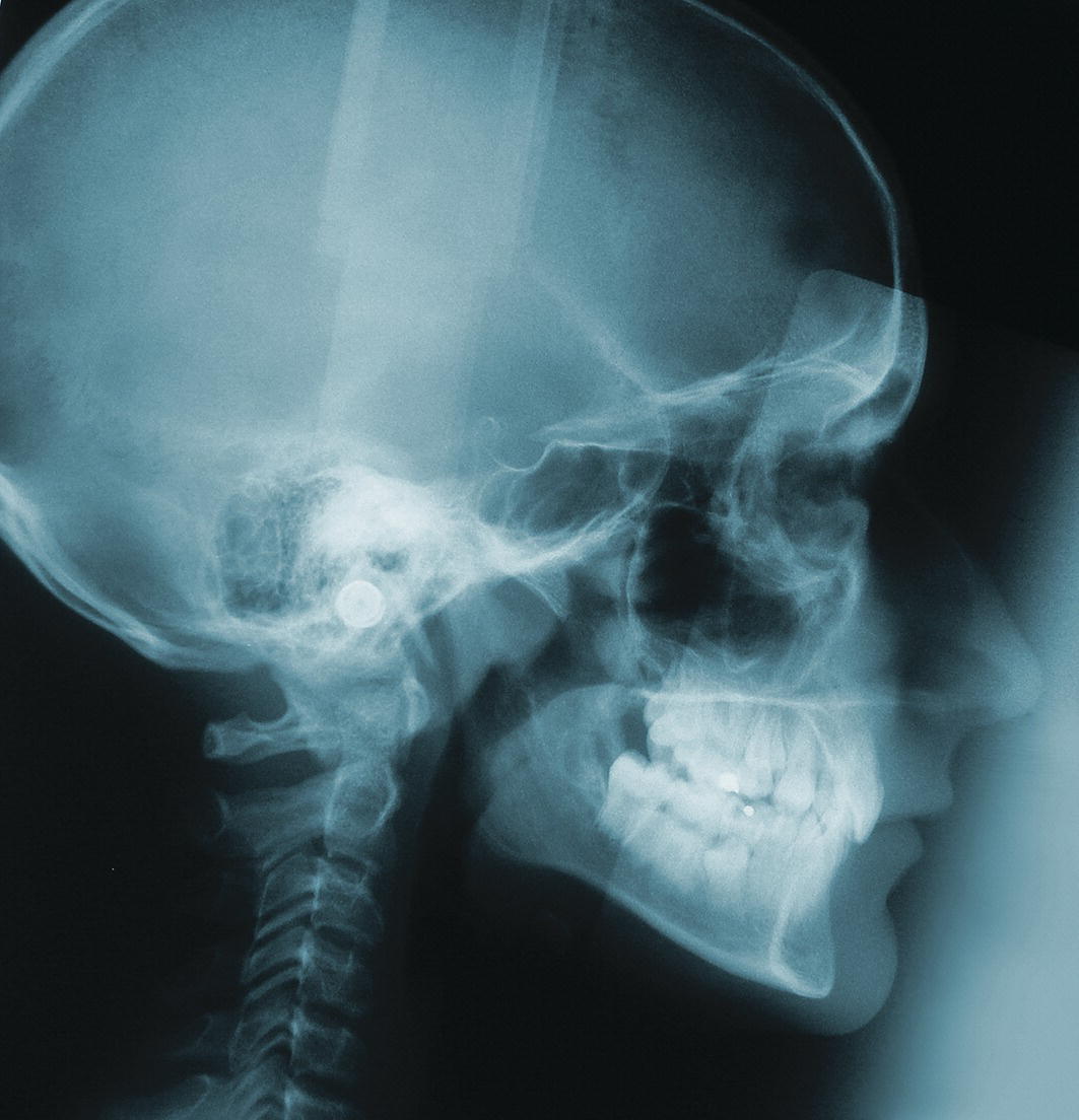
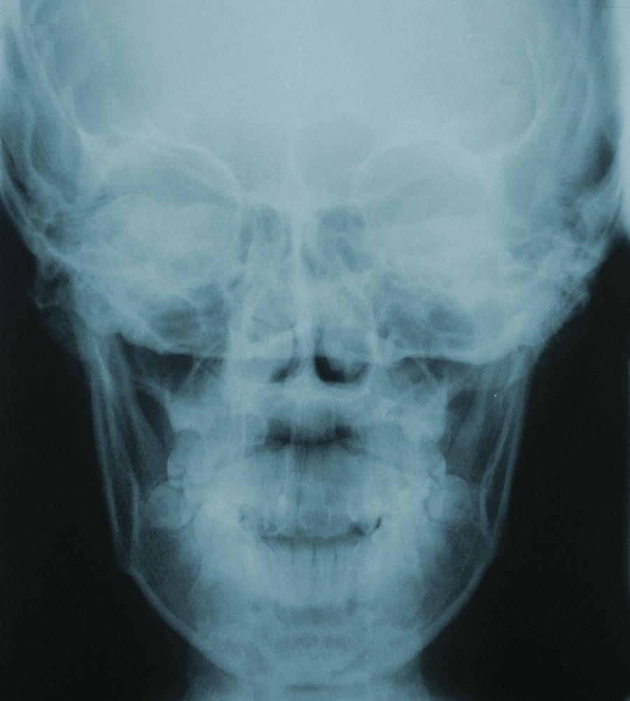
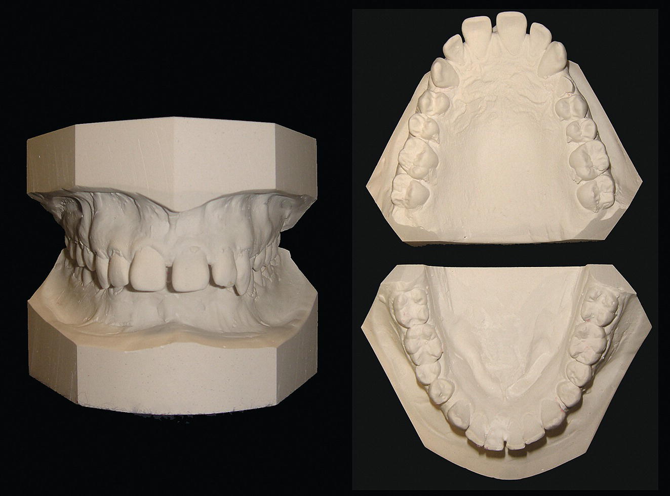
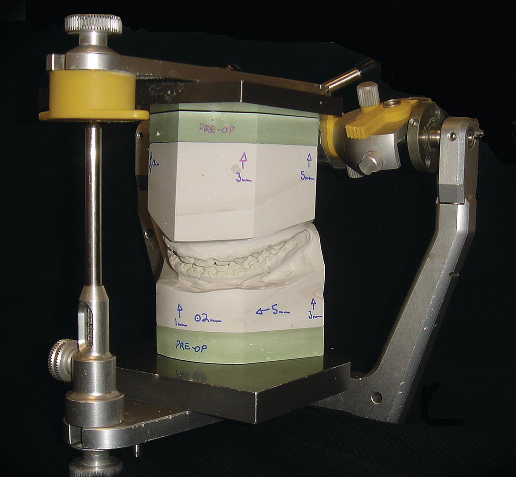
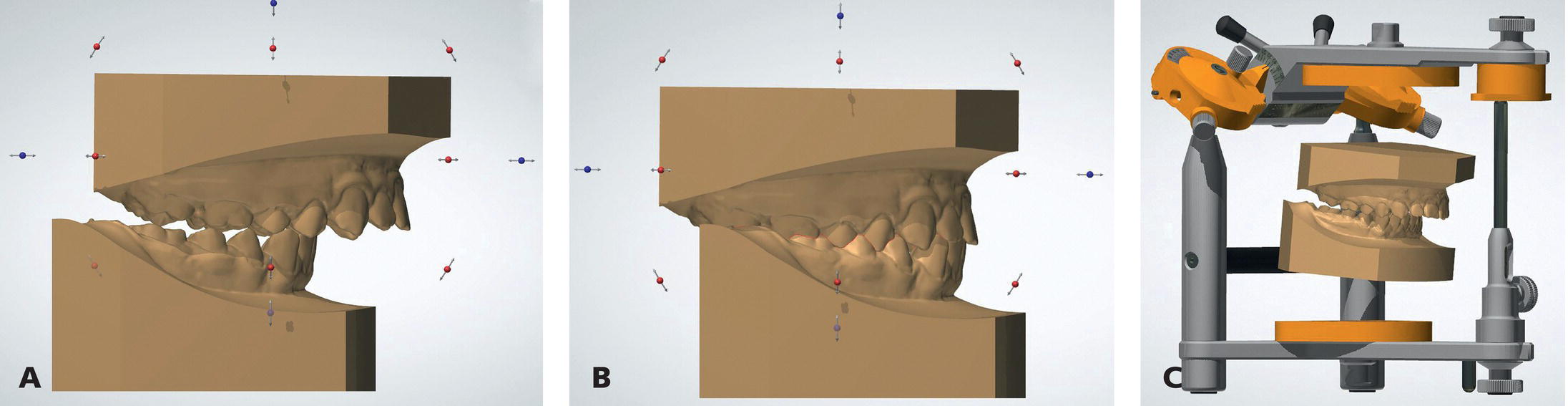
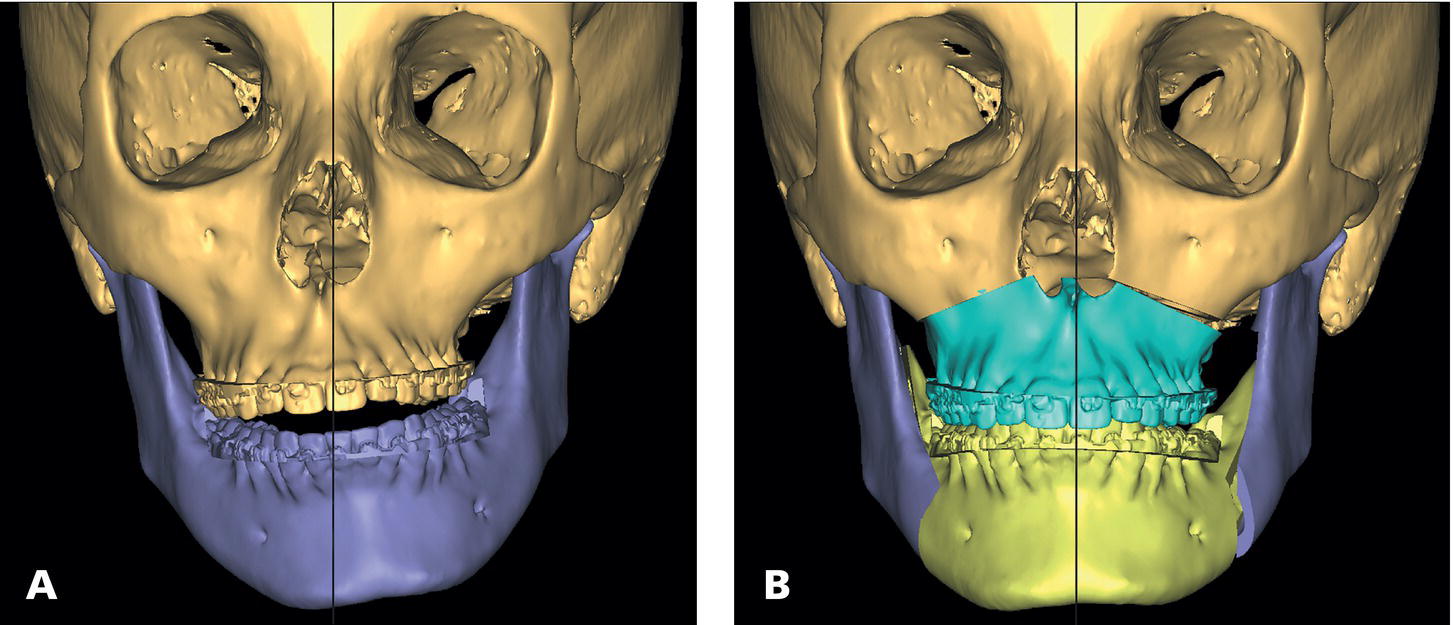
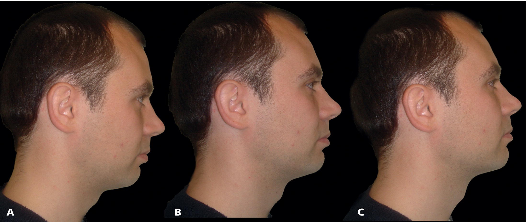
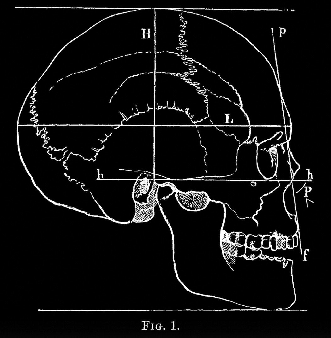
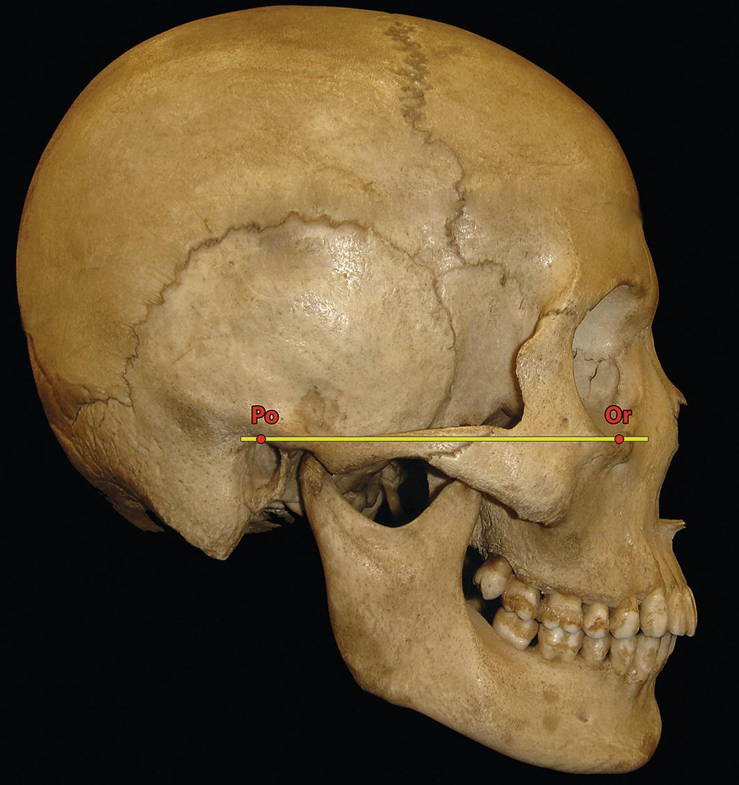
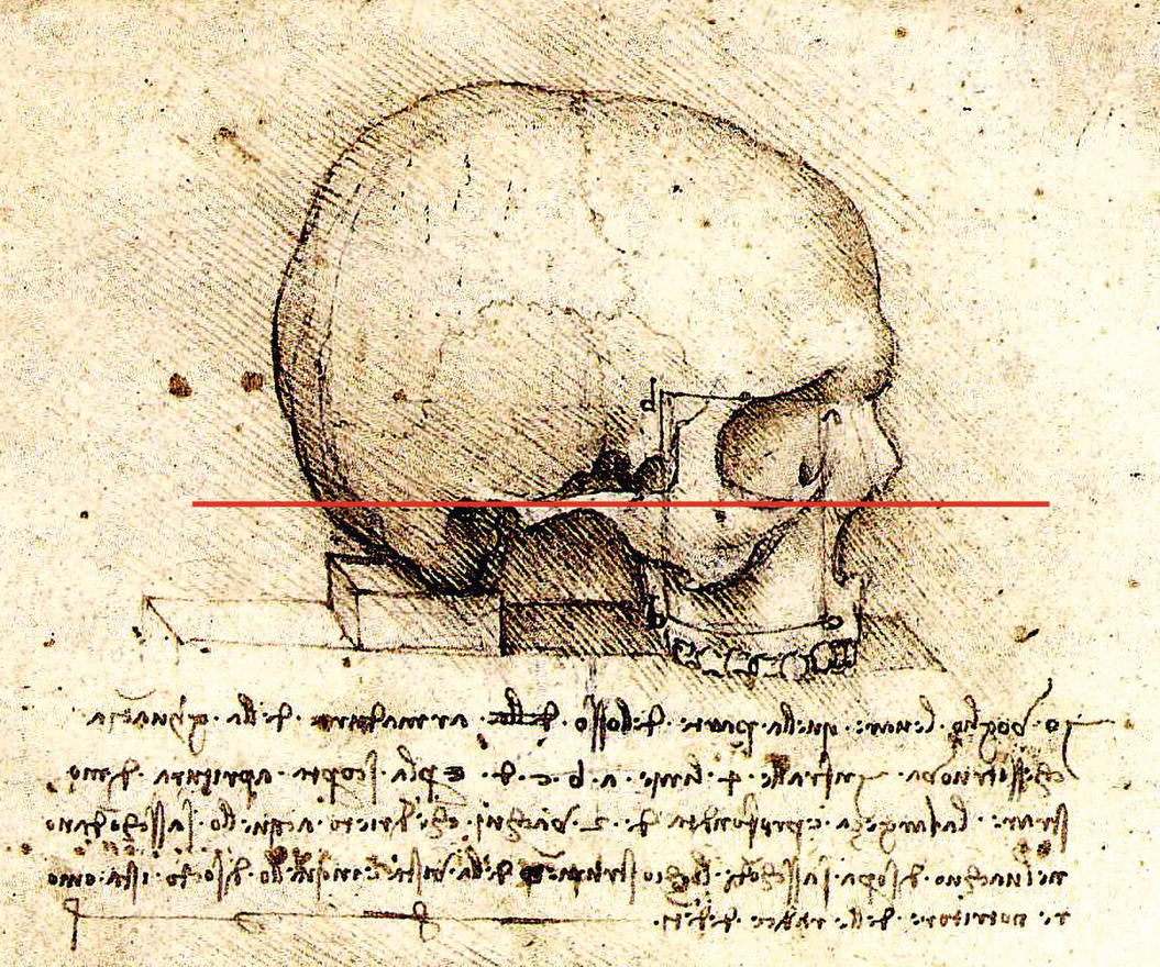
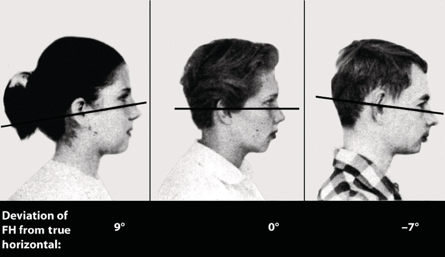
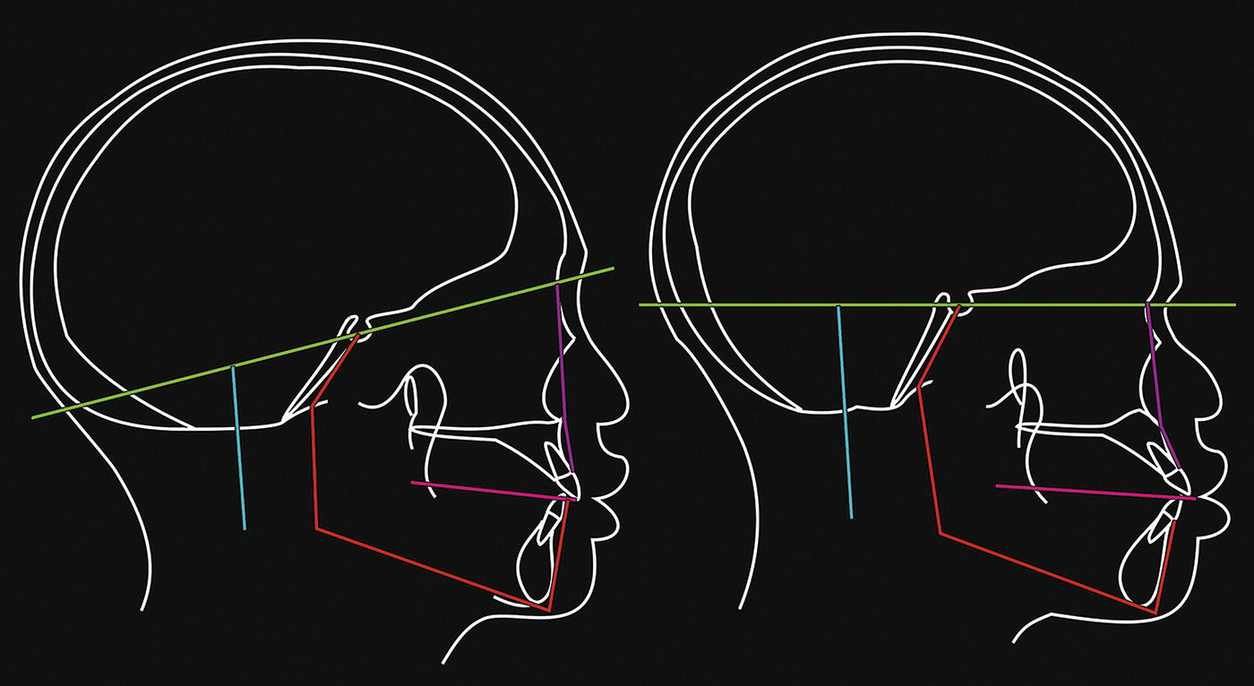
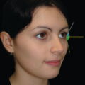
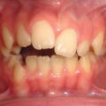
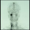
The purpose of this chapter is to provide the information regarding the required diagnostic records and techniques necessary for facial aesthetic analysis. Accurate diagnostic records are an important supplemental tool to clinical patient evaluation in the diagnosis of craniofacial deformities. The purposes of clinical records are: The diagnostic records that may be required are discussed below. Radiographic images form arguably the most important diagnostic records in craniofacial evaluation. The most commonly used radiographic techniques are: The rotational tomograph is alternatively termed the orthopantomograph (OPT or OPG) or dental panoramic tomograph (DPT) (Figure 6.1). The OPT is required for: Figure 6.1 Orthopantomograph (OPT or OPG), alternatively termed a dental panoramic tomograph (DPT). The lateral cephalometric radiograph is a vitally important diagnostic tool. In 1931, Birdsall Holly Broadbent in the USA and Herbert Hofrath in Germany, independently of one another, developed a system of skull radiography with a head‐holding device termed a cephalometer, or cephalostat, which was used to obtain standardized and reproducible craniofacial images on radiographic film (Figure 6.2). The diagnostic uses of the lateral cephalometric radiograph include: Figure 6.2 Lateral cephalometric radiograph; the opacity of the head‐holding ear rods is evident. Figure 6.3 Posteroanterior (PA) cephalometric radiograph. The posteroanterior (PA) cephalometric radiograph may be required in the evaluation of facial asymmetry, forming an important adjunct for qualitative and quantitative dentoskeletal evaluation (Figure 6.3). However, the use of this radiograph has reduced considerably. Most patients with skeletal asymmetries will now be evaluated with three‐dimensional (3D) imaging, such as computed tomography or cone‐beam computed tomography (see later). Extraoral and intraoral colour photographs are required at the start, often during and at the completion of treatment. They are used for: Digital clinical videography captures the dentofacial complex in the dynamic state of animation. This is particularly useful for the following: Study models, or dental study casts, are required in all patients with dental‐occlusal anomalies and those requiring craniofacial surgery that will involve movement of the jaws. The initial impressions should be fully extended into the labial and buccal sulci and record all the erupted teeth. The models are trimmed in a special way (Angle’s trimmed) so that the bases are symmetrical, enabling the occlusion to be evaluated at varying angles with the models placed on a flat surface and making it easier to analyse arch form and arch symmetry (Figure 6.4). The study models should be mounted onto an adjustable articulator (a mechanical device that represents the temporomandibular joints, to which the maxillary and mandibular casts may be attached, with the intention of reproducing mandibular movements), using a facebow transfer (a facebow is a device used to record the relationship of the maxillary dental arch to the condylar hinge axis of the temporomandibular joints), for orthognathic patients requiring maxillary surgery (Figure 6.5). Traditional dental impressions have now been superseded by digital ‘impressions’ taken using hand‐held intraoral digital scanners. When an intraoral scan of a patient’s teeth, palate and gingivae is taken at the chair side, the images are processed by scanning software, which generates an accurate 3D surface model of the dentogingival complex, i.e. virtual study models. This 3D model is displayed on the personal computer (PC) screen at the chair side, and the clinician can see it being generated during the scanning process. Digital study models eliminate the need for storage of plaster study models, reduce waste, and permit computerized analysis and treatment planning. In any circumstances requiring hand‐held study models, e.g. for complex surgical planning, the digital models may be 3D printed, preferably with a biodegradable material. Digital study models may be ‘placed’ on a digital articulator for planning purposes, if necessary (Figure 6.6). Figure 6.4 Dental study casts. Study models have a number of important uses: Figure 6.5 Presurgical dental study casts mounted on an adjustable articulator. Serial height measurements may be plotted onto a growth chart in order to indicate the timing of the adolescent growth spurt and to provide an indication of growth cessation in preparation for orthognathic surgery, as growth in standing height is well correlated with jaw growth (see Chapter 10, Figure 10.41). Computed tomography (CT) is a technique that may be used to generate detailed 3D images of both the hard and soft tissues of the craniofacial complex. Information from CT scans may be used to provide two‐dimensional localized views of the facial skeleton, or 3D computer images that can provide excellent dentoskeletal detail required for the diagnosis of complex dentofacial and craniofacial asymmetry, and for three‐dimensional virtual surgical planning (3D‐VSP) (Figure 6.7) and the creation of surgical stents and 3D printed surgical plates. Three‐dimensional facial soft tissue scans may also be used to evaluate facial soft tissue morphology and to monitor growth or treatment progress by superimposition of serial scans. The main advantage is no radiation exposure and the possibility of combining 3D CT views of the dentoskeletal structures with a 3D soft tissue facial surface scan. Such technology is currently expensive and the systems require further development. Figure 6.6 (A, B) Digital study models may be viewed on a computer screen and manipulated to check dental arch coordination and occlusion for treatment planning. (C) Digital study models ‘mounted’ on a digital articulator. Figure 6.7 Three‐dimensional virtual surgical planning (3D‐VSP) using CT data, demonstrating a jaw asymmetry and anterior open bite pretreatment and with the virtually planned position. Figure 6.8 (A) head tilted down; (B) natural head position; (C) head tilted up. The comprehensive and accurate clinical evaluation of a patient requires that their head is oriented in what is termed natural head position (NHP). The examination of a patient not in NHP may lead to incorrect diagnosis, particularly of chin position and submental anatomy, and result in incorrect treatment planning of required dentoskeletal and soft tissue changes (Figure 6.8). In addition, the clinical records must be taken with the patient in NHP. This is particularly important for the clinical facial photographs, cephalometric radiographs and, where possible, 3D scans. However, despite its importance, the concept of NHP is often misunderstood or altogether ignored. The reason for this is partly historical. Anthropologists in the mid‐to‐late nineteenth century in Germany had been endeavouring for some time to reach a general agreement among themselves as to a method of measuring skulls that could be generally adopted. The purpose was to obtain standardization of the techniques used by physical anthropologists, particularly in order to undertake comparative studies of the crania from various ‘racial’ populations. The outcome of deliberations at two craniometric conferences, held at Munich in 1877 and subsequently Berlin in 1880 was drawn up by Professors Kollman, Ranke and Virchow, and submitted for consideration to the 13th General Congress of the German Anthropological Society held in the city of Frankfurt in 1882. This scheme was adopted and designated the Frankfort Agreement (1882), and published in Germany in 1884.1 Figure 6.9 The Frankfort Agreement was to orient skulls such that the ‘German horizontal plane’, which passed through the ‘lowest point of the under edge of the orbits and the upper edge of the ear‐aperture’ would be horizontal. In this diagram, the plane is denoted as h‐h. The skull ‘profile angle’ (h‐P‐f) is also shown, as the angle that the ‘profile line’ (p‐f) makes with the horizontal. (Modified from Garson1). To compare various crania in a standardized way, it was necessary to place the skulls in a defined position. Therefore, the choice of a horizontal reference plane for the orientation of the skulls, the so‐called ‘German horizontal plane’, was agreed upon, which was defined as follows: ‘That plane which is determined by two straight lines (one on either side of the skull), connecting the “lowest points on the inferior margins of the orbits with the points of the upper margins of the bony auditory meatus situated vertically above their centres”’ (Figure 6.9).1 This was the birth of the use of the Frankfort Horizontal plane (Figure 6.10). Dr John George Garson (1854–1932) was a Scottish anthropologist. In 1882, then a member of the Royal Anthropological Institute, anatomy assistant at the Royal College of Surgeons of England, and lecturer in comparative anatomy at Charing Cross Hospital in London, he attended the 13th General Congress of the German Anthropological Society in Frankfurt and subsequently presented his findings in the UK. He said that he was disappointed with the term ‘our German Horizontal plane’, which had been used by the host delegation throughout the congress, as the plane was a modification of work previously carried out by a variety of researchers from different nations, and because nationalist attitudes tended to reduce the feelings of unity between scientists. Garson concluded his presentation by stressing that the problems with the use of this plane in craniometry meant that he would not recommend its use: Figure 6.10 The Frankfort Horizontal (FH) plane on a dried skull, extending from the superior border of the external acoustic meatus (porion, Po) to the superior border of the inferior orbital rim (orbitale, Or). ‘I refer to the system of measuring the skull in relation to the Frankfort horizontal plane, to which we cannot assent, and which we would fain hope to see abandoned by our brethren in Germany for the more practical method adopted by the majority of anthropologists elsewhere’. [emphasis added] Interestingly, this concluding paragraph of the proceedings of Garson’s presentation was the only use of the term ‘Frankfort Horizontal plane’. In the discussion that followed Garson’s presentation, the eminent anatomist Professor Sir George Thane (1850–1930) said: ‘An attempt was made [in the congress] to ascertain the horizontal and vertical extent of the skull while in its natural position, as it was carried during life. To this proceeding there were many objections, both to the principle itself and to the method of carrying it into practice. Whichever of the many that had been suggested be selected as the horizontal plane of the skull, the position must be an artificial one, for it was well known that all these planes varied more or less in different individuals in their relation to the true horizontal of the head, the visual axis. … With regard to the horizontal that had been chosen, the “German horizontal plane” … the skull when placed as directed was in many cases obviously not in its natural position …’. [emphasis added] With these words, Thane indicated that the term ‘horizontal’, when linked to this anatomical plane, was unrelated to the NHP of a living individual or their skull. The inclination of anatomical planes varied in different people. The following section will discuss the problems that have ensued in facial surgery and dentistry from the misunderstanding of the term ‘Frankfort Horizontal plane’ and its misapplication in clinical practice.2,3 Interestingly, Garson used the spelling ‘Frankfort’ in the name of the ‘Frankfort Agreement’ rather than the usual spelling of the German city of ‘Frankfurt’ where the congress was held. Both variants, Frankfort and Frankfurt, have been used in the literature when referring to the toponymous ‘plane’ ever since. The concept is also unlikely to have been new, as a diagram from the late fifteenth century by Leonardo da Vinci demonstrates a block placed under the occipital bone of a dry skull, and the orientation of the skull is with the Frankfort plane horizontal (Figure 6.11). Figure 6.11 The image shows a cranium, as if resting on a table, supported by a block under the occipital bone, and the orientation of the skull is with the Frankfort plane horizontal. (Detail, Study of the Cranium, Leonardo da Vinci, c. 1489). (Royal Collection Trust/© His Majesty King Charles III 2024.) The use of the Frankfort Horizontal plane was an acceptable compromise for anthropologists studying human crania. However, the use of this plane or any other anatomical reference planes (whether extracranial or intracranial, such as the sella‐nasion [S‐N] plane), to orientate the head of a patient for clinical evaluation, is subject to considerable error. Human anatomy, and thereby all anatomical landmarks, are subject to individual biological variation.2,3 The Frankfort Horizontal plane was chosen by anthropologists as the best anatomical indicator of a physiological position for craniometric studies on skulls. However, living subjects orient their heads in NHP, a physiological position, which feels most natural to them. In many patients, the Frankfort Horizontal plane is horizontal when they are in NHP. However, in some patients, particularly individuals with facial deformities, who fall outside the population norms, the orientation of the Frankfort Horizontal plane may vary quite considerably from the true horizontal when they are in NHP. William Downs, one of the pioneers of orthodontics, advised caution in the use of the Frankfort Horizontal plane in a seminal article, describing the significant individual variation in the inclination of the Frankfort Horizontal plane (Figure 6.12).4 The orthodontist Arne Björk had similarly demonstrated the unreliability of another intracranial reference plane, the S‐N plane.5 Two adult Bantu men with almost identical facial profiles in NHP demonstrated considerable difference in the inclination of the S‐N plane, illustrating the considerable individual variation in the inclination of the anterior cranial base (Figure 6.13). Moorrees and Kean similarly demonstrated that two women with very similar facial profile contours exhibited marked differences in the inclination of the anterior cranial base (S‐N plane) and the Frankfort Horizontal plane (Figure 6.14).6 Figure 6.12 Downs described the significant individual variation in the inclination of the Frankfort Horizontal plane (Modified from Downs4, /with permission of EH Angle Education & Research Foundation.). Figure 6.13 Two adult Bantu men with almost identical facial profiles in natural head position demonstrated considerable difference in the inclination of the S‐N plane, illustrating the considerable individual variation in the inclination of the anterior cranial base. (Modified from Björk5/The Angle Orthodontist.) Natural Head Position (NHP) may be defined as a standardized and reproducible orientation of the head in space when the subject is focussing on a distant point at eye level. In NHP, the visual axis is horizontal. In order to assess facial proportions accurately, patients must be examined in NHP.6 This allows an extracranial vertical, and a horizontal perpendicular to that vertical, to be used as reference lines for facial aesthetic analysis. This is important as the inclination or sagittal cant of all anatomical reference lines, such as the Frankfort Horizontal plane, is subject to individual variation.4–6 The procedure to obtain a clinical facial photograph or cephalometric radiograph in NHP is with the subject standing upright and looking straight ahead into the image of their own eyes in a small mirror located at a distance, at the level of their eyes. NHP has been demonstrated to be reproducible to within 1°–2° over a five‐year period.7
Chapter 6
Clinical Diagnostic Records, Natural Head Position and Craniofacial Anthropometry
Introduction
Clinical diagnostic records
Radiographs
Clinical photographs
Clinical videography
Study models
Serial height measurement
Three‐dimensional hard and soft tissue imaging
Natural head position
The Frankfort Craniometric Agreement and the Frankfort Plane
The Frankfort Agreement
The Frankfort Plane: Historical perspectives
The unreliability of anatomical reference planes
Natural head position: the key to diagnosis
Related posts:


Stay updated, free articles. Join our Telegram channel

Full access? Get Clinical Tree


