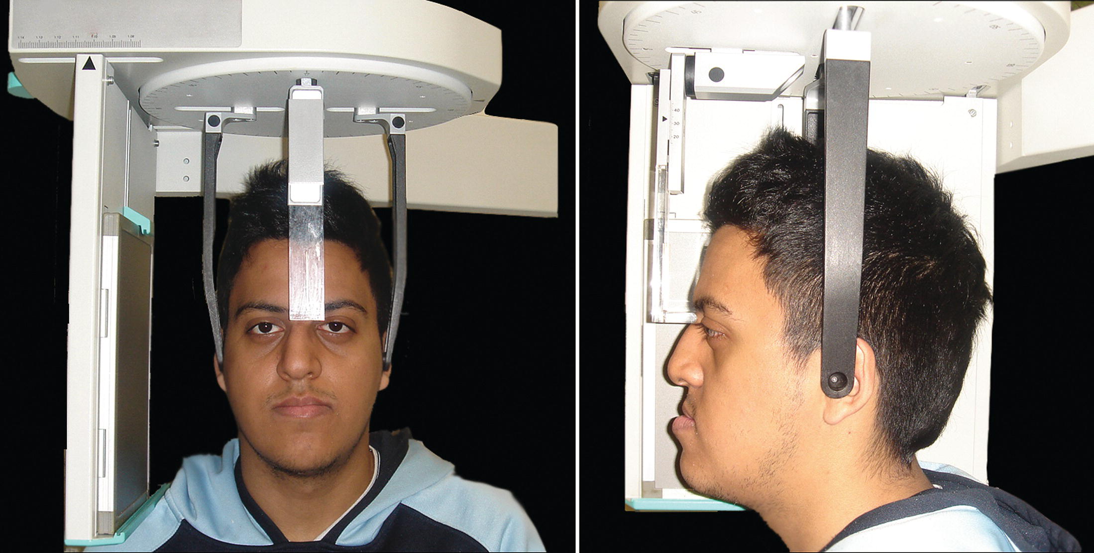
Cephalometry is the scientific measurement of the heads of living individuals (Greek kephalē: ‘a head’; metron: ‘a measure’ or ‘measurement’). Cephalometric radiography is a radiographic technique for measurement of the craniofacial complex; it is closely patterned after craniometry, which is the scientific measurement of dry skulls used in physical anthropology (Greek kranion: skull). The use of skull radiographs in craniometry was first pointed out by August John Pacini (1922) in the USA;1 he demonstrated to anthropologists that accurate cranioskeletal measurements could be made from skull radiographs more easily than from the skull itself. Pacini described the addition of an object of known length to the exposed field and advised the use of a known distance from the X‐ray source to the skull. The head‐positioning device (cephalometer or cephalostat) and the technique of radiographic cephalometry were introduced in 1931 by the orthodontist Birdsall Holly Broadbent (1884–1977) in the USA and Herbert Hofrath (1899–1952) in Germany, simultaneously but independently of one another.2,3 The forerunner to the cephalometer, termed the Reserve craniostat (after Case Western Reserve University Medical School in Ohio), was developed by the English surgeon and anatomist Thomas Wingate Todd (1885–1938) after his appointment as professor of anatomy at Case Western Reserve University Medical School in the USA. Broadbent worked with Todd and helped to modify the craniostat to permit precise standardization of cranial radiographs of dry skulls.4 As a result of his work, Broadbent was assigned to research, under Todd, the cephalic development of children in a study sponsored by the Brush Foundation, which led to the adaptation of the Reserve craniostat to permit radiographs of the heads of living subjects, hence the development of the roentgenographic cephalometer.5 The significance of cephalometric radiography, as opposed to routine skull radiography, was standardization of the technique and reproducibility of the images. The patient is positioned in the cephalometer (or cephalostat) with ear rods placed as a head‐holding device (Figure 7.1). The distance from the X‐ray source to the patient’s midsagittal plane is fixed; the distance from the midsagittal plane to the cassette will be the same for each individual patient. Thus, repeated exposures may be made on successive occasions under standardized conditions. The lateral cephalometric radiograph may be conventionally taken with the patient’s right side (or left side, depending on the country) located nearest the film. The posteroanterior (PA) cephalometric radiograph is taken with the patient facing the film. Figure 7.1 A patient positioned in the cephalometer (or cephalostat) with ear rods placed as a head‐holding device. The facial surface and the underlying craniofacial skeleton have a large number of reference points, or topographic landmarks. An anatomical landmark may be defined as a readily recognizable point that is visible to the human eye, but is not divisible into parts, e.g. nasion or menton. Alternatively, visual landmarks that represent the intersections of lines are termed constructed landmarks (e.g. articulare). Knowledge of the precise location of the landmarks on a cephalometric radiograph is required in order to obtain reliable linear and angular measurements (Tables 7.1–7.3; Figures 7.2–7.4). Points or landmarks joined together continuously in a row form a line.10 A line may be defined in that its length may be divided into parts, but it is so slender that it cannot be divided in width; the Greek mathematician Euclid (fl. c. 300 bc) wrote: ‘A line is length without breadth’.11 An imaginary straight surface on which a group of lines positioned next to one another would lie is termed a plane (Latin planum: flat surface). Planes are, by definition, two‐dimensional. In two‐dimensional analysis of lateral cephalometric radiographs, some authorities only use the term ‘line’ (as transverse and vertical planes in the frontal view are not visible), whereas others use the term ‘plane’ (as a number of cephalometric ‘lines’ may be thought of as ‘planes’), e.g. the line joining sella and nasion, which approximately indicates the anterior cranial base, may be termed the ‘SN line’ or ‘SN plane’. Both terms are acceptable; it is perhaps more important that in analysing two‐dimensional cephalometric radiographs, clinicians think of cephalometric lines as ‘planes’ in their mind’s eye. Specific planes from which the positions of other craniofacial structures are judged are termed planes of reference. The advantage of three‐dimensional (3D) cephalometric images viewed on a computer monitor is that the image may be viewed from multiple perspectives. The analysis of 3D cephalometric images permits the use of solid geometric analysis, as opposed to two‐dimensional plane geometric analysis. Therefore, in addition to linear and angular measurements, volumetric measurements may also be taken (solid geometric analysis). It is important to bear in mind, however, that a thorough understanding of two‐dimensional cephalometric analysis is indisputably important for understanding the craniofacial complex and analysing 3D images. See Table 7.1 and Figure 7.2. Table 7.1 Hard tissue lateral cephalometric (skeletal) landmarks Figure 7.2 Hard tissue lateral cephalometric landmarks (skeletal) (see Table 7.1 for definitions). See Table 7.2 and Figure 7.3. Table 7.2 Hard tissue lateral cephalometric (dental) landmarks Figure 7.3 Hard tissue lateral cephalometric landmarks (dental) (see Table 7.2 for definitions). See Table 7.3 and Figure 7.4. It is useful to compare the definitions of these soft tissue cephalometric landmarks with the anthropometric landmarks described in Table 6.1 (Chapter 6). Table 7.3 Soft tissue lateral cephalometric landmarks Figure 7.4 Soft tissue lateral cephalometric landmarks (see Table 7.3 for definitions). Following the location of the reference points (landmarks), it is possible to draw reference lines/planes. Linear measurements may be made by connecting two landmarks; angular measurements may be made by connecting three landmarks. Numerous lines/planes may be used depending on the cephalometric analysis being employed, and each analysis is based around one or more reference planes (Tables 7.4 and 7.5; Figures 7.5 and 7.6). See Table 7.4 and Figures 7.5 and 7.6. Table 7.4 Hard tissue lateral cephalometric reference planes Figure 7.5 Hard tissue lateral cephalometric (horizontal) reference planes (see Table 7.4 for definitions). Figure 7.6 Hard tissue lateral cephalometric (vertical) reference planes (see Table 7.4 for definitions). See Table 7.5. These lines and planes will be illustrated throughout the chapters in Part II. Table 7.5 Soft tissue lateral cephalometric reference planes Individuals presenting with facial asymmetry require evaluation of the facial skeleton in the frontal view with a PA cephalometric radiograph (Table 7.6 and Figure 7.7). This radiograph is ideally taken with the patient in natural head position (NHP). Identification of the midsagittal plane permits evaluation of bilateral dentoskeletal symmetry. This is followed by identification of bilateral landmarks, which are connected as horizontal lines to form transverse planes; the relative orientation of these planes aids in the evaluation of vertical skeletal asymmetry (Table 7.7 and Figure 7.8). See Table 7.6 and Figure 7.7. Table 7.6 Hard tissue posteroanterior cephalometric landmarks Figure 7.7 Hard tissue posteroanterior (PA) cephalometric landmarks (see Table 7.6 for definitions). See Table 7.7 and Figure 7.8. Table 7.7 Hard tissue posteroanterior cephalometric reference planes (numbers refer to Figure 7.8) Figure 7.8 Hard tissue posteroanterior (PA) cephalometric reference planes (numbers refer to Table 7.7). ‘There is no “royal road” to geometry’. Euclid (c. 300 bc)12 Greek mathematician This was Euclid’s response to Ptolemy I (King of Egypt), when asked if there was an easier way to solve theorems. Cephalometric analysis is essentially applied geometry; i.e. geometry applied to understanding the structural relationships of the craniofacial complex. Cephalometric analysis has an important place in the diagnosis, treatment planning and treatment result analysis of patients with dentofacial and craniofacial deformities. There is a vast array of cephalometric analyses. Each analysis has some merit, yet will not be applicable in all cases. Therefore, no claim can be made for the universal application of any specific analysis. With training, clinicians will become familiar with certain aspects of each analysis, which are useful in the diagnosis of specific facial types and deformities. In addition, time spent in analysing patients using different analyses will teach the clinician to see. When it comes to cephalometric analysis, ‘a little learning is a dangerous thing’. Clinicians must appreciate the geometrical relationships which constitute each aspect of a cephalometric analysis, and not fall into the trap of attempting to ‘treat to cephalometric norms’. Without such a thorough understanding, it is easy to misdiagnose, thereby leading to incorrect treatment planning. ‘The dentoskeletal structures of the face are like The facial skeletal framework is concealed under the facial soft tissue drape. Therefore, in addition to the primary clinical analysis of the facial soft tissue relationships (see Sections 2 and 3), accurate and detailed evaluation of the underlying dentoskeletal pattern requires analysis of the lateral and PA cephalometric radiographs taken in NHP. In highly complex cases, such as severe craniofacial asymmetries or craniofacial syndromes, 3D imaging is also required, although with reduced radiation doses for 3D imaging, and with improvements in 3D virtual surgical planning, 3D analysis is gradually becoming the norm. It must be emphasized that it is the fundamental underlying relationships of the structural components of the facial skeleton to one another and to the craniofacial complex that need to be established and evaluated, with the aid and clarification afforded in using selected parts of relevant cephalometric analyses as diagnostic guides. A thorough knowledge of craniofacial dentoskeletal anatomy is paramount to understanding cephalometric analysis (Figures 7.9–7.12). The facial skeleton is formed of a number of combined morphological/structural components. Although these constituent parts are related to one another and to the overlying soft tissues, they may be depicted and illustrated as distinct for descriptive purposes (Figure 7.13). Individual morphological components may deviate from the norm, yet their combination coupled with variation in the overlying soft tissue thickness and dentoalveolar compensation may result in acceptable facial aesthetics and normal dental occlusion. On the other hand, individual components may be more or less within normal range, yet the particular combination of components may lead to poor facial aesthetics and dental malocclusion. Therefore, measurements of individual morphological components are of no practical significance when assessed in isolation from the overall craniofacial complex. Figure 7.9 Skull (frontal view). It is essential to recognize that most individuals will have variations in the size, shape and relative position of their dentoskeletal structures, and the possible combinations of these morphological components are extremely diverse. Therefore, rather than relying on any simple system of classification, a more effective approach is to describe, sequentially and comprehensively, the arrangement of the various morphological components in relation to one another and to the craniofacial complex. The purpose of this section is to describe the geometric principles required to fully appreciate cephalometric analysis, bearing in mind that clinical evaluation always takes precedence over cephalometric analysis. Ideally, cephalometric analysis will follow, corroborate and add to the clinical evaluation; where this does not occur, further evaluation is required to seek the source of the discrepancy. The results of the various dentoskeletal analyses may be integrated to provide a reasoned and coherent representation of the dentofacial pattern of the individual. Figure 7.10 Skull (lateral view).
Chapter 7
Cephalometry and Cephalometric Analysis
Introduction
Cephalometric landmarks and planes of reference
Landmarks, lines, planes and volumes
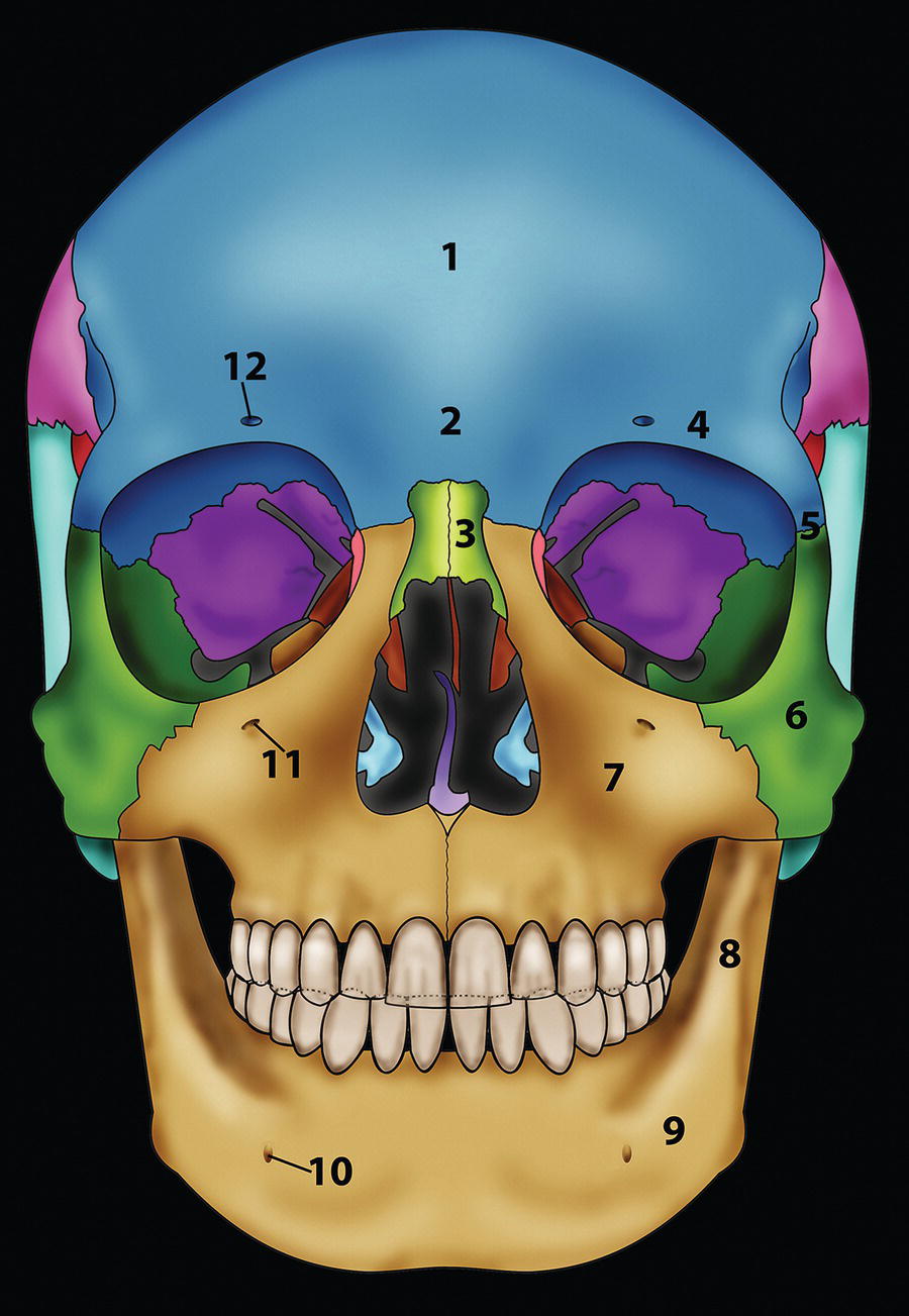
Hard tissue lateral cephalometric (skeletal) landmarks
Landmark (abbreviation)
Definition
Anterior facial landmarks (from superior to inferior)
Glabella (G)
The most prominent point of the anterior contour of the frontal bone in the midsagittal plane, in the supraorbital and frontal sinus region
Nasion (N or Na)
The intersection of the internasal and frontonasal sutures, in the midsagittal plane
Frontonasomaxillary point (FNM or M‐point)
The point at the junction of the nasofrontal and nasomaxillary sutures, designated as M‐point by the craniofacial surgeon Jean Delaire; it is used to construct the ‘superior cranial base line’ by joining M‐point with the apex of the posterior clinoid process (Pcp) in the Delaire craniofacial analysis.6,7
Orbitale (Or)
The lowest point on the inferior orbital rim (bilateral)
Anterior nasal spine (ANS)
The tip of the bony anterior nasal spine; this point corresponds to the anthropological point ‘acanthion’
A‐point (Point A; subspinale)
The point at the deepest midline concavity on the maxillary alveolus between ANS and prosthion
Prosthion (Pr; Supradentale, Sd)
The most inferior anterior point on the maxillary alveolar process, between the maxillary central incisors, in the midsagittal plane
Infradentale (Id)
The most superior anterior point on the mandibular alveolar process, between the mandibular central incisors, in the midsagittal plane
B‐point (Point B; supramentale)
The point at the deepest midline concavity on the mandibular alveolus between infradentale and pogonion
D‐point (point D)
This is the centre of the body of the mandibular symphysis (bony chin) in the midsagittal plane and is estimated visually. The angle SND was described by the orthodontist Cecil Steiner to provide an assessment of the sagittal position of the mandibular skeletal base in relation to the anterior cranial base8,9
Pogonion (Pog)
The most anterior point on the contour of the mandibular symphysis, in the midsagittal plane
Gnathion (Gn)
The most anterior inferior point on the mandibular symphysis (bony chin), in the midsagittal plane. It may be determined by inspection, or constructed as the point of intersection of a vertical tangent to pogonion and a horizontal tangent to menton, extending the bisector through the anterior inferior curvature of the mandibular symphysis
Menton (Me)
The most inferior point of the mandibular symphysis, in the midsagittal plane
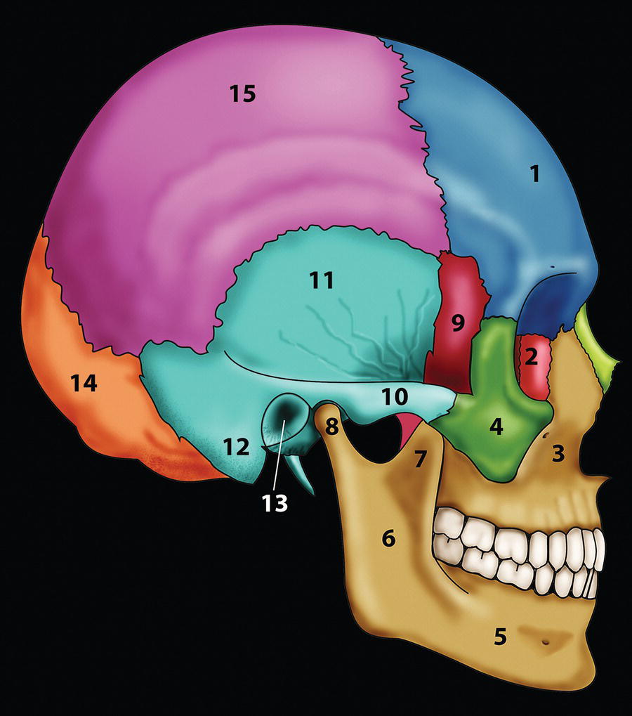
Posterior facial landmarks (approximately from superior to inferior)
Sella entrance point (Se)
The midpoint of the entrance to the sella turcica
Sella (S)
Posterior clinoid process point (Pcp)
The point representing the geometric centre of the pituitary fossa (sella turcica), in the midsagittal plane
The most superior point on the contour of the posterior clinoid process
Porion (Po)
The ‘anatomical’ porion is the most superior point of the outline of the external auditory meatus (bilateral). The use of ear rods in the cephalostat often makes anatomical porion difficult to locate, in which case the superior margin of the glenoid fossa of the temporomandibular joint that lies at the same level may be substituted for constructing the Frankfort Horizontal plane. The term ‘machine’ porion refers to the most superior point of the image of the ear rods, which some authorities use as an alterative
Condylion (Co)
The most posterior superior point on the head of the mandibular condyle (bilateral)
Condylar midpoint (Con)
This is the arbitrary centre of the mandibular condyle in lateral view; it is estimated visually (alternative term is capitulare). An imaginary line through point Con of both mandibular condyles forms the condylar hinge axis around which the mandible may rotate during the initial part of the opening movement
Articulare (Ar)
The point of intersection of the images of the posterior border of the mandibular ramus and the inferior border of the basilar part of the occipital bone (bilateral). It may be used as a substitute for condylion if the latter is not readily discernible; articulare is often the most superior point on the mandibular ramus that can be consistently identified. It was defined by the orthodontist Arne Björk. Any opening or closing movements of the mandible will alter its position.
Basion (Ba)
The most inferior point on the anterior margin of the foramen magnum, in the midsagittal plane
Opisthion (Op)
The most inferior point on the posterior margin of the foramen magnum, in the midsagittal plane
Bolton point (Bo)
The highest point on the upward curvature of the outlines of the retrocondylar fossae of the occipital bone, approximating the centre of the foramen magnum; named by the orthodontist B Holly Broadbent in honour of the philanthropist Charles B Bolton2
Pterygomaxillare superius (Ptms)
The pterygomaxillary fissure is a bilateral teardrop‐shaped area of radiolucency, the anterior surface of which represents the posterior surfaces of the maxillary tuberosities. The landmark is the most superior point of the pterygomaxillary fissure (bilateral)
Pterygomaxillare (Ptm)
The most inferior point at the junction of the anterior and posterior borders of the pterygomaxillary fissure (bilateral); this point is in very close proximity to PNS
Posterior nasal spine (PNS)
The most posterior point on the bony hard palate, in the midsagittal plane. It may be located by extending the anterior wall of the pterygomaxillary fissure inferiorly to intersect the hard palate
Gonion (Go)
The most inferior posterior point on the contour of the angle of the mandible (gonial angle). It may be determined by inspection, or constructed as the point of intersection of the posterior ramal plane and mandibular plane, extending the bisector through the curvature of the gonial region of the mandible (bilateral)
Hyoid point (Hy)
The most anterior superior point on the body of the hyoid bone, also termed ‘hyoidale’ 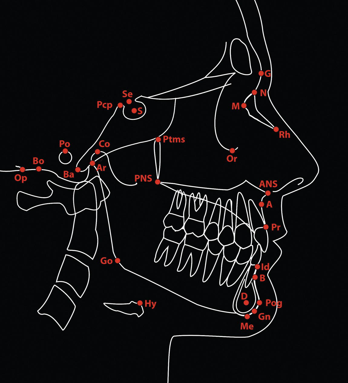
Hard tissue lateral cephalometric (dental) landmarks
Landmark (abbreviation)
Definition
Centre of resistance (Cr)
The midpoint of the root axis of the most prominent maxillary incisor (see note below)
Incision superius apicalis (Isa)
The root apex of the most anterior maxillary central incisor
Incision superius incisalis (Isi)
The tip of the incisal edge of the most labially positioned maxillary central incisor crown
Incision inferius incisalis (Iii)
The tip of the incisal edge of the most labially positioned mandibular central incisor crown
Incision inferius apicalis (Iia)
The root apex of the most anterior mandibular central incisor
Mx6.mbc
The mesiobuccal cusp tip of the maxillary first permanent molar crown
Mn6.mbc
The mesiobuccal cusp tip of the mandibular first permanent molar crown 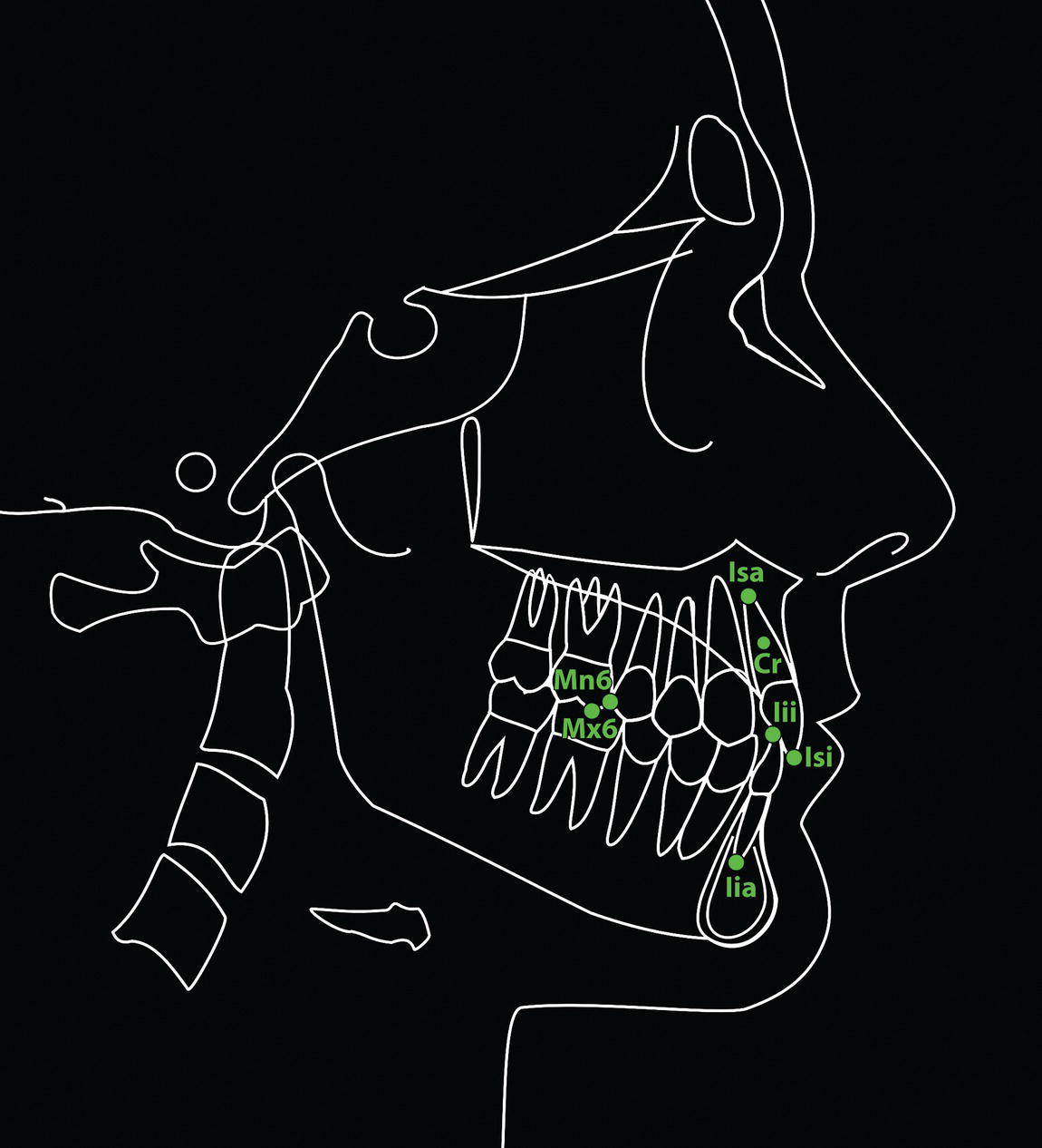
Soft tissue lateral cephalometric landmarks
Landmark (abbreviation)
Definition
Glabella (G‘)
The most prominent point of the soft tissue anterior contour of the forehead in the midsagittal plane, in the supraorbital brow ridge region, in the midsagittal plane
Nasion (N′ or Na‘)
Cephalometric soft tissue nasion is usually the point of deepest concavity of the soft tissue contour of the root of the nose, in the midsagittal plane. Soft tissue nasion (N′) and skeletal nasion (N) should be at the same vertical level. In some individuals there is an anterior curvature of the superior portion of the nasal bones; in such patients the deepest point of the nasal radix is termed ‘sellion’ (or ‘subnasion’), which is inferior and usually posterior to soft tissue nasion
Rhinion (Rh‘)
The soft tissue point overlying the caudal end of the nasal bones in lateral view, marking the osseocartilaginous nasal junction
Pronasale (Prn)
The most prominent point of the nasal tip, in the midsagittal plane
Subnasale (Sn)
The point where the base of the nasal columella meets the upper lip, in the midsagittal plane
Soft tissue A‐point (supralabiale, Spl)
The point of greatest concavity of the facial contour of the upper lip between subnasale and labrale superius, in the midsagittal plane
Labrale superius (Ls)
The point representing the mucocutaneous vermilion border of the upper lip, in the midsagittal plane
Stomion superius (Sts)
The most inferior point of the upper lip, in the midsagittal plane
Stomion (St)
The most anterior point of contact between the upper and lower lip, in the midsagittal plane. If the lips are held apart in repose, a superior and inferior stomion point may be distinguished
Stomion inferius (Sti)
The most superior point of the lower lip, in the midsagittal plane
Labrale inferius (Li)
The point representing the mucocutaneous vermilion border of the lower lip, in the midsagittal plane
Soft tissue B‐point (sublabiale, Sbl)
The point of greatest concavity of the facial contour of the lower lip between labrale inferius and soft tissue menton. It is the deepest point of the mentolabial fold
Pogonion (Pog‘)
The most anterior point on the contour of the soft tissue chin, in the midsagittal plane
Gnathion (Gn‘)
The most anterior inferior point on the soft tissue chin contour, in the midsagittal plane. It may be determined by inspection, or constructed as the point of intersection of a vertical tangent to soft tissue pogonion and a horizontal tangent to soft tissue menton, extending the bisector through the anterior inferior curvature of the soft tissue chin pad
Menton (Me′)
The most inferior point of the soft tissue chin, in the midsagittal plane
Cervical point (C)
The innermost point between the submental region and the anterior surface of the neck, in the midsagittal plane. It is located at the intersection of a horizontal tangent to the submental plane and a vertical tangent to the anterior neck plane 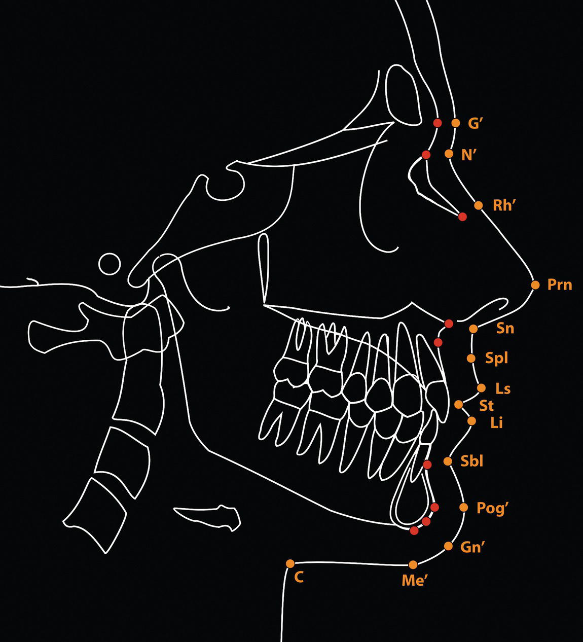
Cephalometric planes of reference
Hard tissue lateral cephalometric reference planes
Landmark (abbreviation)
Definition
Horizontal reference planes
Sella entrance to nasion (Se‐N) plane
A line joining the sella entrance point (Se) to nasion
Delaire horizontal line (superior cranial base line)
A line joining M‐point with the apex of the posterior clinoid process (Pcp); described by the craniofacial surgeon Jean Delaire6,7
Sella‐nasion (S‐N or SN) plane
A line joining sella and nasion, approximately indicating the anterior cranial base
Optic plane
The ‘supraorbital plane’ is drawn tangent to the superior contour of the anterior clinoid process and the roof of the orbit; the ‘infraorbital plane’ is drawn tangent to the lower border of sella turcica and the floor of the orbit; the ‘optic plane’ bisects the angle formed by the supraorbital and infraorbital planes; described by the orthodontist Viken Sassouni as an alternative to the Frankfort Horizontal plane31
Frankfort Horizontal (FH) plane
A horizontal line connecting the cephalometric landmarks porion and orbitale
Constructed Frankfort Horizontal (FHc) plane
A horizontal line drawn through sella at 7° less than the sella‐nasion line; described by the orthodontist Charles Burstone15
Maxillary plane (MxP; palatal plane)
A line joining posterior nasal spine (PNS) and anterior nasal spine (ANS)
Occlusal plane (OP)
A line on the cephalometric radiograph representing an imaginary plane at the level of the dental occlusion. Three distinct planes may be defined:
Mandibular plane (MnP)
A line/plane connecting gonion and menton, representing the inferior border of the mandible in the sagittal plane; the mandibular plane may also be drawn as a tangent to the inferior border of the mandible
Vertical reference planes
Nasion perpendicular (N‐perpendicular)
A line drawn perpendicular to the Frankfort Horizontal (or ideally the TrH) plane from nasion; described by the orthodontist James McNamara Jr
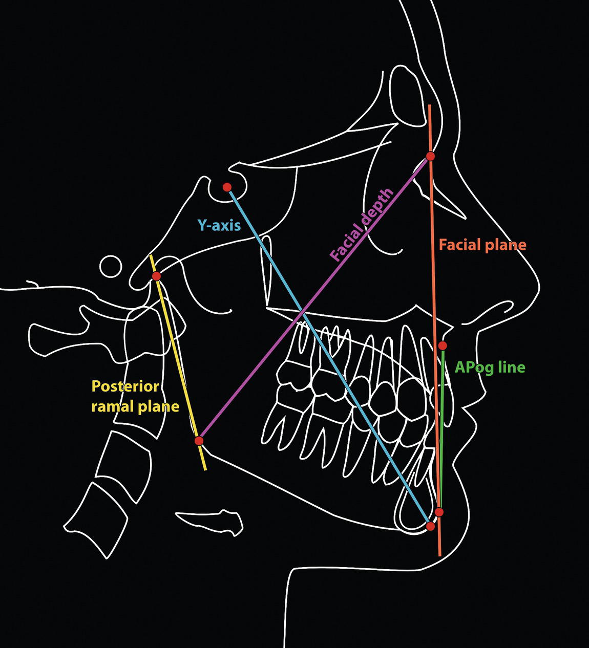
Facial plane (skeletal)
A line joining nasion to pogonion
Delaire vertical line
The ‘craniofacial balance line’ described by Delaire is a vertical line dropped from a point slightly posterior to M‐point along the M‐Pcp horizontal line (the point representing the articulation of the frontal process of the maxilla with the lacrimal bone); in an attractive ‘Caucasian’ profile this line is said to pass through the nasopalatine foramen and bony menton, thereby determining the sagittal position of the maxillary and mandibular skeletal bases6,7
A‐Pog line
A line connecting maxillary point A to bony pogonion; described by the orthodontist Robert Ricketts, used in the Downs analysis and popularized by Raleigh Williams (1969)28
Y‐axis
A line joining sella and gnathion
Facial depth line
A line joining nasion and gonion
Posterior ramus plane
This plane is tangent to the posterior border of the mandibular ramus 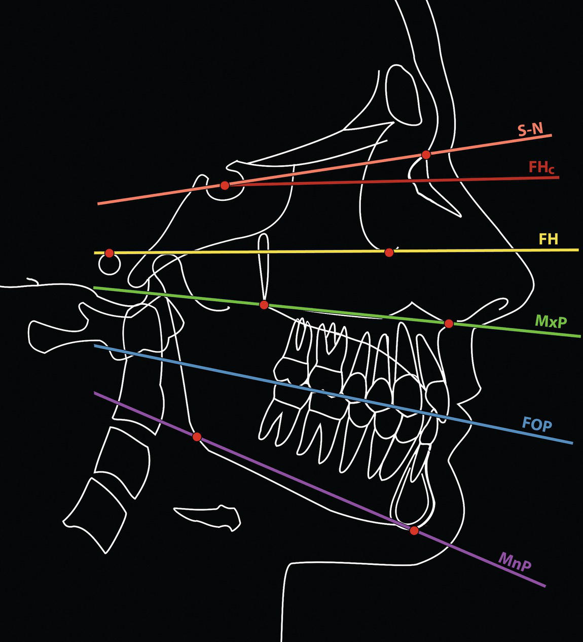
Soft tissue lateral cephalometric reference planes
Landmark (abbreviation)
Definition
E‐line (‘Aesthetic’ line/plane of Ricketts)
Described by the orthodontist Robert Ricketts,27,33 a line tangent to the chin (pogonion) and nasal tip (pronasale); it is used to analyse the prominence of the lips
Facial plane (soft tissue)
A line joining soft tissue nasion to soft tissue pogonion
H‐line (Harmony line of Holdaway)
Described by the orthodontist Reed Holdaway,34,35 the H‐line (Harmony line) is drawn from soft tissue pogonion (Pog‘) tangent to the upper lip (Ls)
Rees aesthetic plane
Described by the plastic surgeon Thomas D Rees,36 this is a line tangent to the nasal tip (pronasale) and upper lip (labrale superius), which should pass near the bony pogonion in an attractive facial profile
Riedel plane
Described by the orthodontist Richard Riedel,16 a line tangent to the upper lip, lower lip and soft tissue pogonion; its advantage is that it eliminates the nasal prominence from the analysis
S‐line (Steiner line)
Described by the orthodontist Cecil Steiner,8,9 the S‐line is drawn from the midpoint of the S‐shaped curve between subnasale (Sn) and pronasale (Pn) to soft tissue pogonion (Pog‘). It is used to analyse the prominence of the lips
Sn‐Pog‘ line (Burstone)
Described by the orthodontist Charles Burstone,15 the subnasale to soft tissue pogonion line may be used to evaluate lip prominence. The advantage is that it eliminates the nasal prominence from the analysis
Zero degree (0°) meridian (Gonzalez Ulloa)
Described by the plastic surgeon Mario Gonzalez Ulloa,37,38 it is a vertical line dropped from soft tissue nasion, perpendicular to the Frankfort Horizontal plane
Z‐line (Merrifield)
Described by the orthodontist Levern Merrifield,39 the profile line, or Z‐line, is drawn tangent to soft tissue pogonion (Pog‘) and to the most prominent point of either the lower or upper lip, whichever is most prominent. Ideally, the upper lip should fall on the line and the lower lip should be slightly behind. The angle formed by the intersection of this profile line and the Frankfort Horizontal (FH) plane (or ideally the TrH plane) is referred to as the Z‐angle
Posteroanterior cephalometric radiography
Hard tissue posteroanterior cephalometric landmarks
Landmark (abbreviation)
Definition
Midline landmarks
Crista galli (Crg)
The most superior point of the crista galli
Anterior nasal spine (ANS)
The centre (tip) of the bony anterior nasal spine
Incision superius frontale (Isf)
The midpoint contact between the maxillary central incisors at the level of the incisal edges
Incision inferius frontale (Iif)
The midpoint contact between the mandibular central incisors at the level of the incisal edges
Menton (Me)
The most inferior midpoint on the inferior border of the mandibular symphysis
Bilateral landmarks
Eurion (Eu)
The most prominent lateral point on the side of the skull in the region of the parietal and temporal bones; it is the most lateral point on the cranium
Latero‐orbitale (Lo)
The intersection of the lateral orbital contour with the ‘innominate’ line; the innominate line represents the tangentially viewed temporal surface of the greater wing of the sphenoid
Medio‐orbitale (Mo)
The intersection of the medial orbital contour with the superior contour of the lesser wing of the sphenoid
Zygion (Zy)
The most lateral point on the zygomatic arch
Maxillare (Mx)
The intersection of the lateral contour of the maxillary alveolar process and the inferior contour of the zygomatic process of the maxilla
Mx6.bs
The most prominent lateral point on the buccal surface of the first permanent maxillary molar
Mn6.bs
The most prominent lateral point on the buccal surface of the first permanent mandibular molar
Mastoidale (Ms)
The most inferior point of the mastoid process
Mental foramen (Mf)
The centre of the mental foramen
Gonion (Go)
The most inferior, posterior and lateral point at the angle of the mandible
Antegonion (Ag)
The most superior point in the antegonial notch 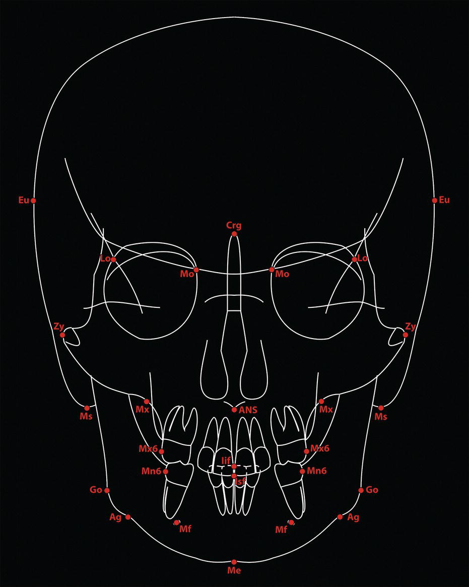
Hard tissue posteroanterior cephalometric reference planes
Landmark (abbreviation)
Definition
Vertical reference planes
Midsagittal plane
A vertical line drawn through crista galli and nasion, parallel to a true vertical line; it should pass through ANS, between the central incisor teeth and through menton
Horizontal reference planes
1
Superior transorbital plane
A line connecting the most superior point on the contour of the left and right superior orbital outlines
2
Inter latero‐orbitale plane
A line connecting the left and right latero‐orbitale (Lo) points
3
Inter medio‐orbitale plane
A line connecting the left and right medio‐orbitale (Mo) points
4
Transpetrous plane
A line connecting the most superior point on the outline of the left and right petrous part of the temporal bone
5
Interzygomatic plane
A line connecting left and right zygion (Zy) points
6
Inferior transorbital plane
A line connecting the most inferior point on the contour of the left and right inferior orbital outlines
7
Intermaxillare plane
A line connecting left and right maxillare (Mx) points
8
Occlusal plane
The transverse occlusal plane may be evaluated by a line connecting the left and right maxillary and mandibular buccal molar cusps; there may be separate maxillary and mandibular planes in the presence of lateral open bites
Canine line
A separate maxillary and mandibular canine line may be drawn connecting the left and right canine cusp tips
9
Incisal line
A separate maxillary and mandibular incisal line may be drawn tangent to the incisal edges
10
Intergonial (bigonial) plane
A line connecting the left and right bony gonion points at the mandibular angles
11
Inter mental foramen plane
A line connecting the centre of the left and right mental foramina; this landmark is easier to identify on three‐dimensional reconstructions
12
Inferior chin plane
A line drawn on the inferior border of the chin through menton, with maximum bone contact 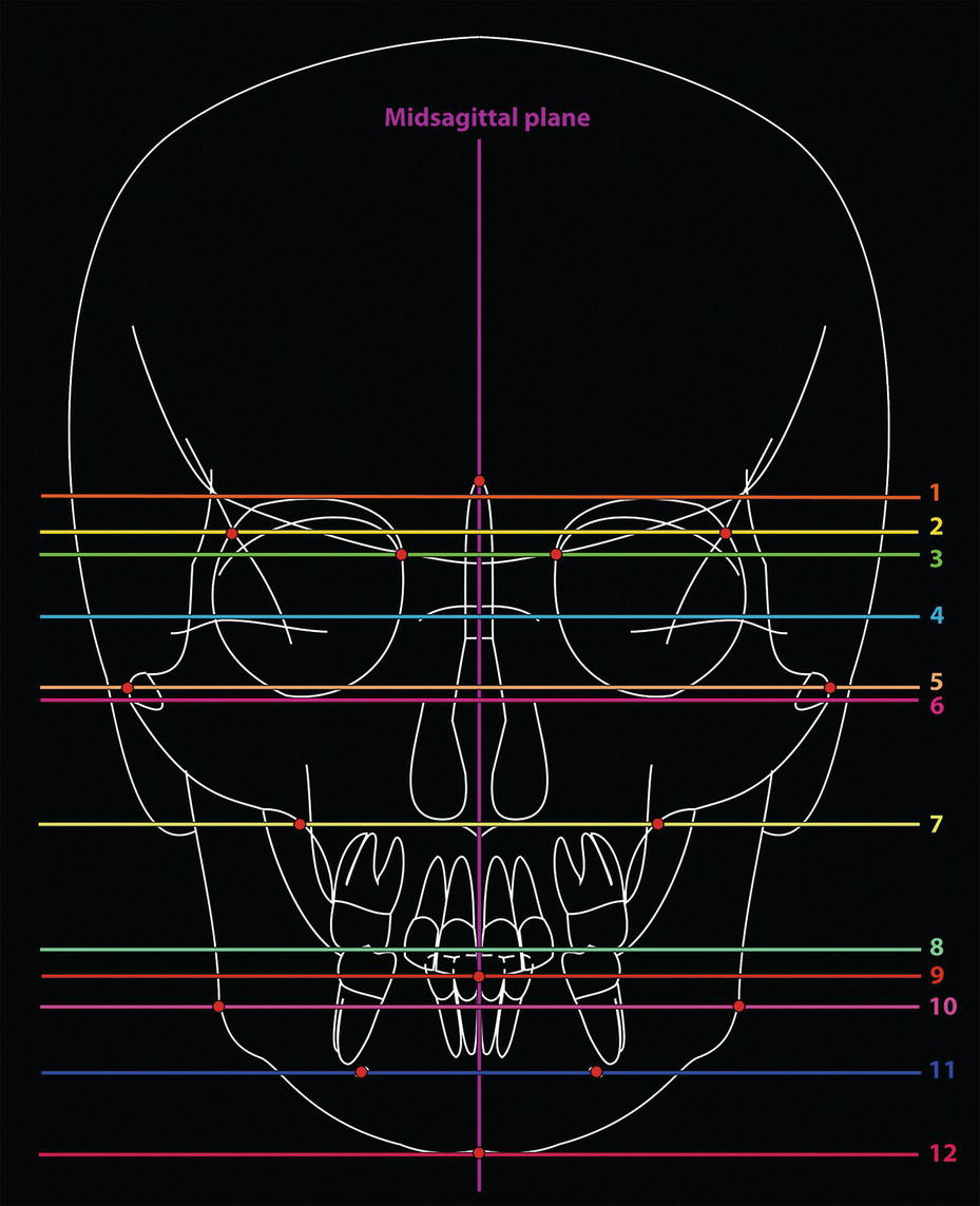
Cephalometric analysis and geometric principles
Description of dentofacial deformities
the scaffold over which the soft tissues drape’.13

Related posts:


Stay updated, free articles. Join our Telegram channel

Full access? Get Clinical Tree


