Fig. 12.1
Relationship between impedance (Z), reactance (X c), resistance (R) and frequency of an applied electrical current. Biological tissue presents specific Z, R and X c for each applied frequency (e.g. Z 1, Z 2, Z 3). The loci of R and X c for a range of frequencies plot a semicircle, eponymously known as a Cole plot. Experimentally measured data are fitted to this theoretical semicircle to allow estimation of resistance at the otherwise immeasurable frequencies of zero (R 0) and infinite (R ∞) Hz. R 0 is the measure of extracellular fluid, including lymph, volume

(12.1)
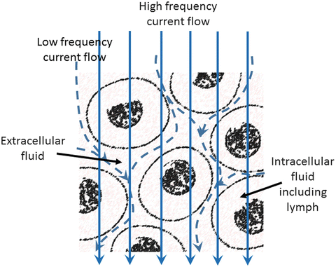
In BIA, the applied current is an alternating current, i.e. with a sine wave of a given frequency, typically 50 kHz. In BIS, alternating currents are applied over a range of frequencies, typically between 5 and 1000 kHz. At low frequencies, the capacitive nature of cell membranes is such that they present a barrier to current flow and current flows only through the extracellular fluids while at high frequencies current can pass across the cell membranes and current flows through both intra- and extracellular water, i.e. total tissue water (Fig. 12.2). Thus in Eq. (12.1) if R is the measured resistance at a low frequency, ideally zero (R 0), then the volume of the extracellular fluid may be calculated if the resistivity of extracellular fluid and the conductive length is known.


Fig. 12.2
Representation of the frequency-dependent flow of an applied electric current through biological tissue. At high frequencies, ideally infinite frequency but generally considered to be any frequency greater than 50 kHz, current can cross the cell membrane and hence flows through total tissue water. At low frequency, ideally zero frequency or below approximately 10 kHz, current cannot pass across the cell membrane owing to the capacitive nature of the bi-lipid structure of the membrane. Consequently current flows only through the extracellular fluid. Resistance measured at a low frequency is therefore a measure of extracellular fluid volume. With permission from Impedimed
Application of Bioimpedance Spectroscopy in Lymphoedema
The concept underlying the use of BIS to assess lymphoedema is that lymph is an extracellular fluid. Consequently, if the lymph content of a tissue or body region changes, this should be reflected in a change in the electrical resistance measured at a low (zero) frequency. One of the earliest publications to suggest the use of BIS for lymphoedema quantification was the work of Watanabe et al. in 1989 [4], but the approach was not systematically developed until some years later with the publication of Ward et al. [5]. The reasons for this delay were both practical and analytical. At this time there were no suitable impedance analysers commercially available; instruments were developed by research groups for their sole use. In the early 1990s two companies, Xitron and SEAC, both now incorporated in the one company ImpediMed, simultaneously developed BIS analysers. The analytical problems were twofold. Extracellular fluid including lymph is optimally quantified from the resistance measured at zero frequency (R 0). Unfortunately, a number of technological and safety issues preclude being able to measure R 0 directly. Instead R 0 is estimated by modelling the impedance data obtained from measurements made within the practical measurement region of 5–1000 kHz. The development of theoretical models and availability of computer programs at this time allowed for the first time the ready estimation of R 0 [6]. An additional problem is readily seen from consideration of Eq. (12.1). In order to quantify volume, resistivity and true conductor length are required. In biological systems both are unknown. The linear distance between the measurement points on the body is used as a surrogate for l while an apparent value for resistivity can be approximated from empirical studies. However, since both are approximations to the true values, their use can introduce error into the prediction of volume. Consequently, an index approach was adopted to “quantify” lymphoedema. In a manner analogous to use of inter-limb volume differences to assess unilateral limb lymphoedema, the ratio of R0 values between an at-risk or affected tissue region and a comparable unaffected region was used as a measure of the excess intracellular (lymph) volume [5]. This approach continues to be used to this day [7, 8].
Assessment of bilateral lymphoedema requires a different approach that makes use of BIS’ ability to distinguish between intra- and extracellular water. Lymphoedema is considered to be purely accumulation of extracellular water; the intracellular water compartment volume remains unchanged. Consequently in lymphoedema, the ratio of extra- to intracellular water increases; this ratio in an affected body region can be indexed or standardised against the equivalent ratio in an unaffected body region, for example, the ratio observed in affected legs in bilateral lymphoedema is compared to the “normal” ratio found in the unaffected arms of the same individual [9].
Bioimpedance Spectroscopy for Assessment of Lymphoedema in Practice
Choice of Instrument
Many different impedance analysers are commercially available. They fall into two main groups according to the type of electrical connection to the body: stand-on and lead devices. Stand-on devices are rarely used for lymphoedema assessment and will not be discussed further. Lead type devices can be further categorised according to the number of frequencies of measurement. Single frequency devices are designed primarily for body composition analysis and are generally not recommended for lymphoedema assessment since they operate at 50 kHz, a frequency too high to quantify specifically extracellular fluid although they have been used for this purpose with some success [10]. Preferred devices are spectroscopic (BIS) instruments that enable measurement of R 0 [11].
Subject Preparation
For measurement, the subject should ideally be lying down with the limbs slightly abducted from the body with no contact between limbs. Measurements may be made in the seated position but, owing to fluid shifts in the body due to gravity, small but significant differences in impedance between seated and supine measurements are found. Consequently, measurements made in patients in different postures are not directly comparable. Once the instrument leads are connected to the appropriate electrodes, measurement of impedance takes only a few seconds and during this time the subject should refrain from making any movement. Measurements should always be made in replicate and outlying values discarded.
Electrodes
Universally, commercially available BIS instruments are designed as tetra-polar instruments. In theory, the impedance of a conductor can be measured with the use of a pair of electrodes that span the conductor of interest; each electrode acts to apply the electric current and, using, separate circuitry, also to measure the opposition to the flow of current. This approach is not suitable in most biological applications since it measures the total impedance between the electrodes. This includes not only the deep tissue impedances, i.e. of tissue fluids, but also the much larger contact impedance at the interface between the electrode and the skin surface. This contact impedance can be mitigated by separating the measurement or sensing circuitry and the current application circuitry. In this arrangement, the region of interest is spanned by a pair of sense or measurement electrodes with the current being applied by a pair of distally located current electrodes.
Precise electrode design varies with instrument manufacturer but all adhere essentially to the same basic design; a conductive material coats a flexible plastic sheet and is covered with a sticky conductive gel of silver–silver chloride. This type of electrode is common in electrocardiography applications. The impedance instrument is attached to the electrodes by light-weight wire leads and crocodile clips.
The site of electrode attachment to the skin should be well cleaned with an alcohol wipe prior to measurement particularly if oil-based skin creams are likely to have been used. Both the measurement of impedance and the transmission of current through the skin rely upon the naturally conductive nature of normally hydrated skin. Dry or papery skin is not uncommon in the elderly and it may be necessary to use extra conductivity (ultrasound) gel to obtain good electrical contact in such individuals. The electrode sites should be free of jewellery such as watches and bracelets particularly if made of conductive materials.
Electrode Locations
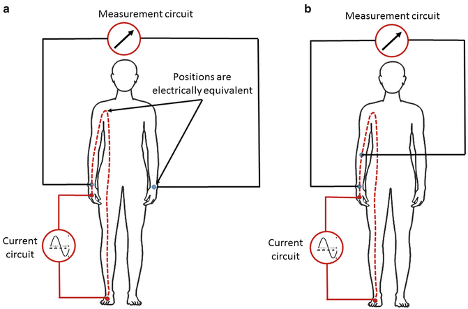
The precise body sites for electrode application are generally determined by what is desired to be measured, but the guiding principles are that the sense electrodes span the region of interest, that the sites are easily anatomically identifiable and reproducible and that the body extends distally to provide sites for application of the current drive electrodes. The most common applications of BIS are for assessment of limb, either arm or leg, lymphoedema. Consequently, sense electrodes are typically located at the wrist and ankle with current drive electrodes placed at the base of the toes and fingers. It is recommended that manufacturers’ instructions specific to their impedance instruments and electrodes are consulted. In order to measure the arm or leg, in addition to the sense electrode at the wrist and ankle respectively, the second electrode sense electrode needs to be placed proximally along the limb. In early studies, these were located using either the acromion or anterior superior iliac spine as easily identified and reproducible sites. However, subsequent research found that, based on the principle of equipotentials, better precision of measurement could be obtained by using electrodes located on the contralateral wrist or ankle (Fig. 12.3a). If an intermediate segment of a limb, for example the forearm only, is to be measured, sense electrodes are located at a defined distance apart along the limb (Fig. 12.3b). Current drive electrodes can remain on the hand and foot as the only requirement is that current flows past the site of the sense electrodes. Measurement of non-cylindrical regions of the body such as the breast or hand requires arrangements of electrodes particularly suited to the anatomically irregular shape of these regions [12, 13]. Irrespective of measurement region, it is imperative that electrodes are placed with the greatest care and attention to reproducibility of location particularly where data are to be expressed as ratios between limbs; electrodes must be identically located on both limbs.


Fig. 12.3
Electrode locations for the measurement of whole arm impedance utilising the principle of equipotentials (a) and for the measurement of sub-limb segment, e.g. the forearm (b). Distally located electrodes (red circle) on the foot at the base of the toes and hand at the base of the fingers provide the current drive circuit. In figure a electrodes (blue circle) precisely located on the wrist on the mid-line between the bony prominences provide the impedance measuring sites. In the example shown, the impedance of the right arm is being measured with the electrode at the left wrist being electrically equivalent to a point at the junction of the arm and torso. Although the precise point is not known, it will be identical for each arm. For measurement of the left arm, these electrode positions are a mirror image. The same principle for locating electrodes can be applied to the legs. In figure b, the location of electrodes is shown for measurement of a segment of the arm. In this case the equipotential approach is not used and the location of the two measurement electrodes (blue circle) defines the measured volume
Contraindications for Use
Stay updated, free articles. Join our Telegram channel

Full access? Get Clinical Tree


