8. Fifty Years of Progression in Facelifting and Neck Lifting
The search for perfection in facial rejuvenation continues. Dr. Connell’s pursuit of improved results in facelift surgery represents a classic, informed, and pragmatic approach to surgical design. His underlying compulsion to accurately diagnose and ask why has shaped his career.
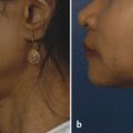
The facelift technique that was universally used when he was in residency in the 1950s at the Mayo Clinic involved deep-layer plication and excision of excessive skin. Fig. 8.1 shows work by Dr. Connell typical of his early practice (1952–1960) in which a facelift was accomplished by precise plication at multiple points of the investing fascia and neck defatting. The result is notable for its absence of the later, more successful jowl and neck correction. The brow lacks successful rejuvenation; however, using the techniques current in that era, he delivered not only a respectable result but also one lacking the surgical stigmata sometimes common to that period of surgical plication. No distortion of hairline or preauricular anatomy is present, and the skin rests naturally over the face.
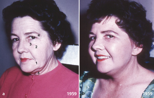
Not satisfied with then-current techniques, the younger Dr. Connell began tackling the surgical incisional stigmata typified by hairline shift and poor skin-color matches. His intuitive skill at limiting an observer’s ability to detect evidence of surgery would become the hallmark of his early work and reputation.
8.1 Preservation: Incision Design
Connell’s good results followed redesign of incision placement, closure technique, and preservation of normal anatomical facial boundaries, proportions, and relationships. He was inspired by the writing of Dr. Raul Loeb of Brazil, who published observations that identified natural-appearing surgical earlobe reattachment. The normal-appearing earlobe was determined to be approximately 10 to 15 degrees posterior to the long axis of the ear. Re-creation of this earlobe angle avoided the tethered, forward-swept, elflike ear often caused by surgically induced skin tension with conventional facial suspension and closure. 1 , 2 , 3 , 4 , 5 , 6 By preserving inclination of earlobe attachment, along with producing improved neck contours, his early evolution from the 1950s to the 1970s permitted maximal rejuvenation with minimal detectability of surgery.
8.1.1 Details and Planning of Incisions
Temporal Incision
While riding the Paris Metro as a young surgeon, Connell observed that a hairless gap of greater than 3 or 4 cm from the lateral orbit to the temporal hairline imbued an additional 10 years of age to any face, young or old. Similarly, he noted that surgical elevation of the sideburn above the root of the helix results in an aging appearance. 1 , 3 , 4 , 6
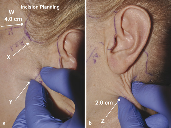
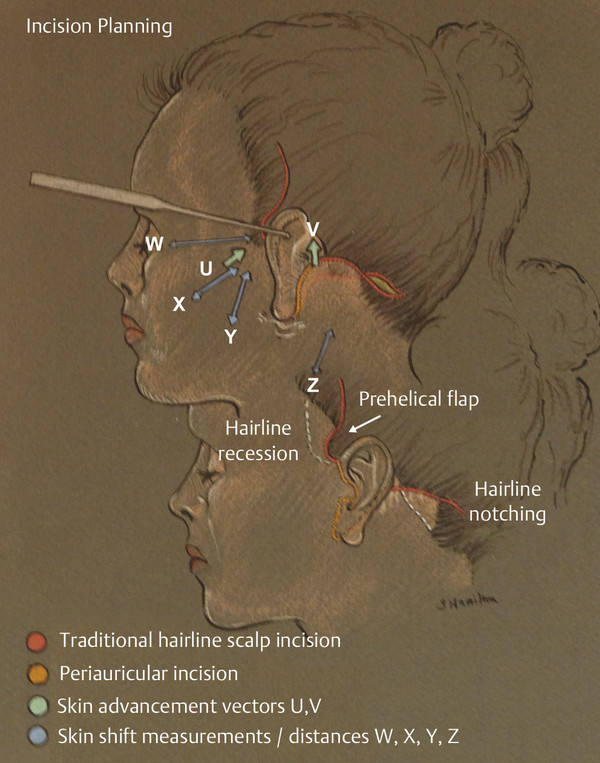
He believes that preoperative, precise evaluation of expected skin shift should guide the choice of either a temporal incision into a hair-bearing temporal scalp location if a minimal shift in hairline superior or posterior is expected, or a hairline or intertrichial incision if the hairless space would be surgically expanded beyond 4 cm. Often one sees swept-back hair in preoperative pictures and swept-forward hair in postoperative photographs that intentionally obscure temporal hairline and ear details. Regrettably, these patients can never comfortably wear their hair back or up. Entire lifestyles that are active and outdoor based may be impacted by the visible stigmata of this hairline shift. A “pinch test” perpendicular to the temporal hairline and sideburn along the axes of expected skin shift (Fig. 8.2) will quickly predict the temporal expansion of hairless facial skin or the probability of overelevation of the preauricular sideburn above the base of the helix. 3 , 4 , 6
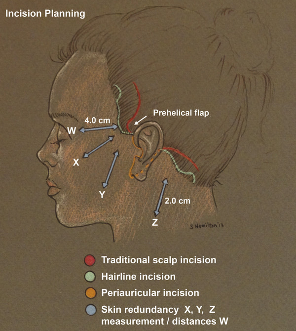
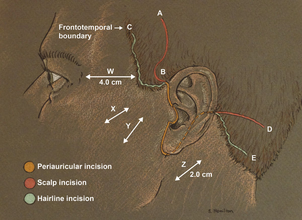
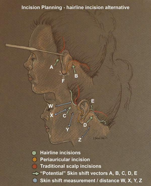
Connell modified the classic temporal hair-bearing scalp incision at its origin in the prehelical hairline with a small semicircular anterior deflection, or prehelical flap (Fig. 8.3 and Fig. 8.4). The flap originates at the origin of the sideburn, beginning at the root of the helix, then continuing its arc in the temporal hair-bearing scalp. This “rescue” flap mitigates the formation of an unsightly notch, or hairless zone, intruding into the temporal hairline just at or above the root of the helix (Fig. 8.5). 4 , 5 , 6 The alternative incision follows the anterior temporal hairline or intertrichial approach and is used when an expected skin shift would expand the orbitotemporal open area beyond 3.5 to 4 cm and terminates superiorly in a small posterior incisional deflection placed before the temporal hair thins to wispy hair at the frontotemporal boundary (Fig. 8.6). The posterior deflection allows for later inset into a recipient bed created just posterior to it during closure to direct the terminus of the incision away from the sparse zone of the upper temple and reduce detectability. 1 , 6 A fine hairline incision will preserve more ideal facial ratios and add to minimizing detectability and maximizing natural-appearing rejuvenation, 6 7 (Fig. 8.7).
Preauricular Incision
As part of his reevaluation of the status quo in the 1960 to 1970s, Connell broke the preauricular anatomy into subunits. He determined that helix width, pretragal hollow, tragal height, superior and inferior intertragal notches, and the earlobe–cheek junction were subunits of the preauricular aesthetics that would require preservation in incision design. He reduced the number of color shifts from face to ear by careful placement of the incision within the distances defined by the simple observation of the patient’s ear anatomy and pigmentation pattern (Fig. 8.8). Incisions anterior to the natural facial and ear color shift can create multiple color shifts and become an emblem of surgery and the operated look. 5 , 6
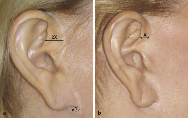
As shown in Fig. 8.9, the uppermost portion of the incision begins one helix width (Fig. 8.9) anterior to the posterior border of the helix beginning at the facial–helical junction. The incision then gently curves into the superior intertragal notch to the edge of the tragus.
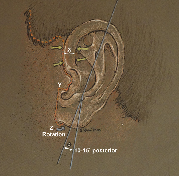
In the lower one-fifth of the tragus, Connell devised a transverse flap (Fig. 8.9 y, point Y), which exits at 90 degrees from the posterior tragal edge and moves anterior across the tragus. Once it reaches the crease between the anterior lobule and the cheek, the incision turns 90 degrees again to liberate the earlobe while preserving a 2- to 3-mm cuff of facial skin to avoid closure of the earlobe to the face. 6 (Fig. 8.9). Failure to preserve the earlobe–cheek junction frequently results in a “stuck-on” appearance of the ear. Later, this hairless, thin cuff of tissue will provide a more natural transition and point of union with the advanced thicker, pigmented, sometimes hair-bearing facial skin and the thin, delicate ear skin closure. Without preservation of the delicate earlobe facial sulcus, no technique exists that will re-create this aesthetic, visible landmark of normalcy.
The Retroauricular Incision
Some teaching advocates a retroauricular incision onto the concha with the intended goal of prevention of a downward and posterior drift of the retroauricular incision postoperatively into the visible mastoid area. Unfortunately, placement of the incision more anterior on the concha makes it likely that downward tension will occur, as a result of greater obligatory vertical neck skin excision inherent with this approach. Connell chose to place the incision directly into the auriculomastoid groove and preserve rather than obliterate it (Fig. 8.5). He also thought that placement of the incision over the concha might lead to an unnatural webbing deformity across the auriculomastoid groove and risk the loss of another attractive landmark and delicate sulcus often appreciated when observing an individual from behind. 6 As stated, placement onto the concha throws the incision anterior and creates an obligatory vertical shift of neck skin to close. In contrast, the ideal shift of neck–retroauricular skin is tangential to the anterior neckline region to obtain the best redrape of redundant anterior tissue, to correct horizontal excess, and to reduce unwanted vertical skin excision. Significantly excessive vertical shift of neck skin will create an unplanned vertical skin deficit with resultant postoperative tension. Postoperatively, when the patient sits up, tension at the auriculomastoid incision will increase as the neck undergoes flexion and the shoulders naturally drop. While on the operating table, patients’ shoulders are relatively higher, and their neck is positioned commonly in some degree of extension, which gives a false impression of excess vertical skin to many surgeons. Thus, maintaining neutral head position and avoidance of an incision design that promotes vertical shifts of the neck skin are the keys to avoiding excessive vertical skin excision, incisional tension with poor scarring, and unsightly hair shifts. 6 , 7
The earlobe should be an attachment point, not a pivot point. Unnatural infralobular fullness can occur when the preauricular facial flap is rotated toward the ear anteriorly and the postauricular flap is also rotated toward the ear posteriorly. The convergence effect of these flaps creates fullness at the earlobe attachment and is detectable as a facelift with unnatural infralobular fullness (Fig. 8.6, point F). With a precise shift of neck skin 90 degrees to the neckline, almost no neck-flap skin will require trimming along the anterior flap edge as it moves up along the auriculomastoid groove for closure behind the ear. 6
Occipital Incision
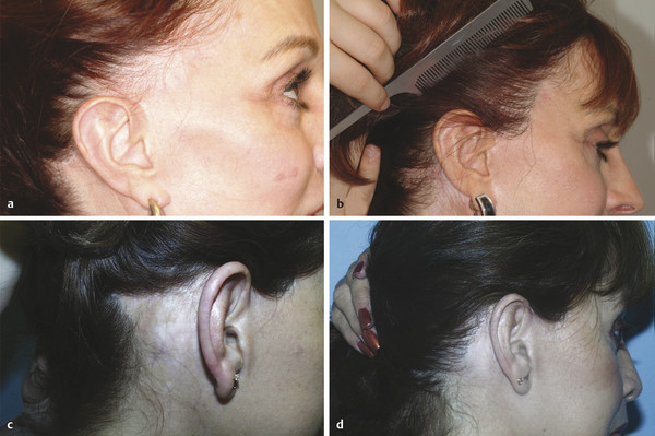
This region is similar to the temporal incision design. As in the temple, if greater than 2 cm of hair shift is measured and expected to be advanced, then a hairline occipital incision should be used(Fig. 8.3 and Fig. 8.4). The incision terminates with a curved posterior deflection above the sparser occipital hair at the nape. As in the temple, the terminal post/superior deflection of the occipital incision is inset into the scalp by creation of a recipient site. Failure to anticipate a significant skin shift with an incision in the hair of the masto-occipital scalp will guarantee movement of hairless neck skin into the occipital hairline with masto-occipital hairline notching and posterior occipital hairline elevation (Fig. 8.7 a, c). 1 , 5 , 6 , 7
Connell advocates no singular approach, but instead one based on clinical assessment, expected shift, and preservation of a normal hairline.
Submental Incision
Many “traditional” approaches have long advocated placing this incision in the submental crease (Fig. 8.10 a). 6 , 8
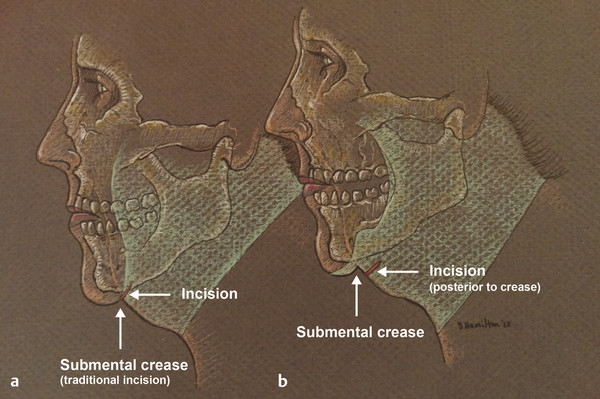
The submental incision should be placed posterior to the crease 1 to 2 cm, and its length generally is 2.5 cm (Fig. 8.10 b). 5 , 6 Lengthening the incision requires manual elevation of the cheek skin bilaterally to test whether planned incision length would move onto visible territory. Connell’s posterior incision placement, rather than placement at the submental crease, makes attention to these deeper, lower structures easier.
8.2 SMAS Flap Design—History
During the 1960s, Connell focused on incisional improvements and redesign. All too often the plicated investing fascia flattened cheek contours and widened the intermalar distance by gathering tissue laterally. Fixed suturing to plicate the superficial musculoaponeurotic system (SMAS) from orbit to ear also placed important permanent and supportive sutures in visible areas of the face rather than the facial boundaries he used later. Visible lumpiness, puckering, and distortion across these load-bearing plication sutures were additional stigmata Connell designed his SMAS technique to bypass by moving important points of SMAS tension and fixation sutures (Fig. 8.11).
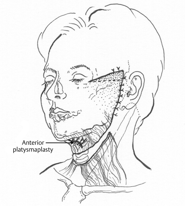
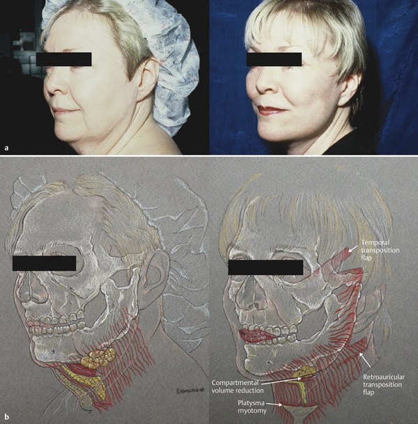
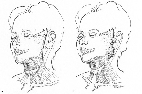
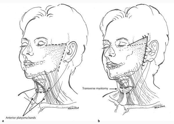
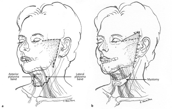
He observed that lateral platysmal attachment to the sternocleidomastoid (SCM) fascia exerted a corrective force on the submental anatomy, but correction of submental laxity was additionally improved by direct submental platysmal invagination (Fig. 8.12, Fig. 8.13, and Fig. 8.14). Connell and others, such as Dr. Rex Peterson and Dr. Jose Guerrerosantos, began dynamically releasing the platysma by complete or partial division to create a permanent and clear aesthetically pleasing release of a tight or tethered platysma. The added benefit of platysma transection was the permanent release of anterior or lateral platysmal banding and increased mobilization for improved suspension (Fig. 8.12, Fig. 8.15, Fig. 8.16, and Fig. 8.17). With age, the platysma will bowstring away from the angular submental contour that in youth is close to 90 degrees and in midlife can elongate or dehisce to a straight line from menton to sternal notch, effectively bowstrung into a 45-degree profile from chin to lower neck. Without division, any corrective suturing and tension will be overcome eventually.
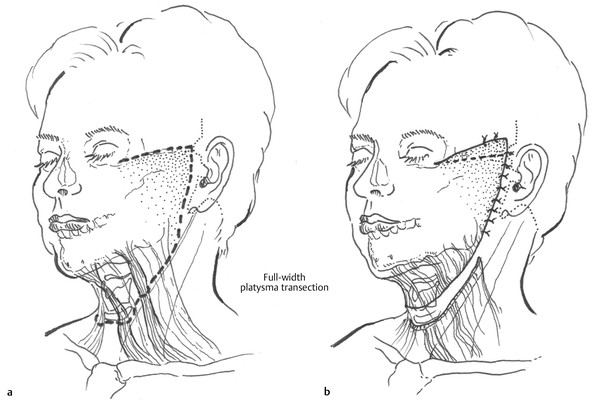
Curiously, it was likely his early awareness of the powerful corrective force of platysma release that led Connell to release its fascial projection across the anterior face. This layer was identified incidentally by many surgical innovators of that time, including Tessier and Connell, and was immortalized in the classic article by Mitz and Peyronie, who worked with Tessier and coined its eponymous name. The term SMAS, rather than investing fascia, entered the lexicon of facelift surgeons everywhere. 9
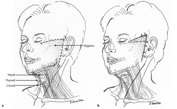
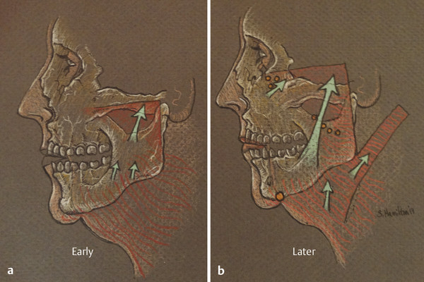
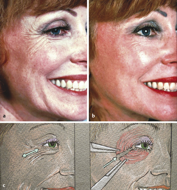
Connell’s early elevations of the facial SMAS in continuity with the platysma reached no higher than a line parallel to and just below the lower border of the zygoma (Fig. 8.18). Results from that period show improved jowl and submental correction, but little or no midface rotation or periorbital correction is evident. From the 1970s to the 2000s, he reasoned through these limitations and, with an uncanny knowledge of facial microanatomy, redesigned his SMAS release to occur above the zygoma, where most literature warned of a high risk of frontal branch injury. As the era of midface elevation and lower eyelid filling populated the podiums of meetings in the 1980s and 1990s, Connell offered an effective solution to provide midface rotation, elevation of the depressed lid–cheek junction, and correction of infraorbital hollowing with the higher vector of SMAS supportive force associated with division of this layer above the zygoma. He further refined the high-SMAS release to include a crow’s-foot correction, or lateral orbicularis oculi myotomy. Similar to platysma division, his concept of dynamic release was applied to an obstacle to further refinement and restoration of a more youthful periorbital appearance. By dynamically releasing the orbicularis oculi, along with greater eyelid skin undermining, greater periorbital rotation and shortening of the perceived lower eyelid length occurred by a pleasing elevation of the lid–cheek junction. Realizing that the lateral orbicularis oculi frequently functioned as a depressor of the lateral brow (or depressor lateralis), his design of dynamic release of the sometimes powerful lateral orbicularis helps elevate the temporal brow, reduce crow’s feet, and shorten the vertically depressed aging lower eyelid (Fig. 8.19). What follows is a description of his final flap design to resuspend ptotic facial tissue and structures without any assistance from pulling on the thin, aged facial skin flaps as had been advocated in Connell’s day and persists in current times. Instead, he chose to observe that in his opinion the sole function of the skin was to cover, never support, the face; and any deviation from that truth would invite creation of a pulled, artificial appearance.
Related posts:
 6. Facial Sculpting and Facial Slimming with Neurotoxins
 22. Lower Eyelid Blepharoplasty
 17. Secondary Facelifting
 5. Energy-Based Treatments for Facial Aging
 9. Male versus Female Facelift Surgery. Is There a Difference?
 12. Primary Superficial Musculoaponeurotic System (SMAS) Facelift and Neck Lift
Stay updated, free articles. Join our Telegram channel

Full access? Get Clinical Tree


