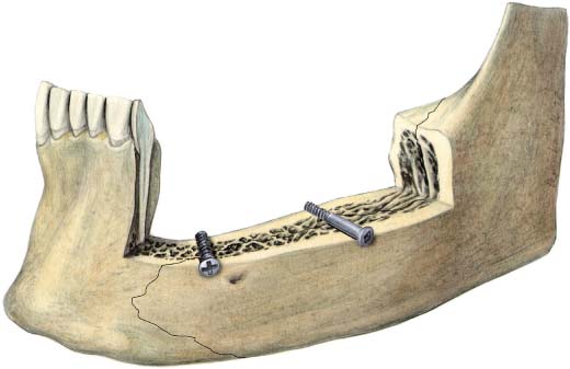
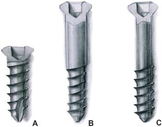
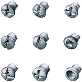
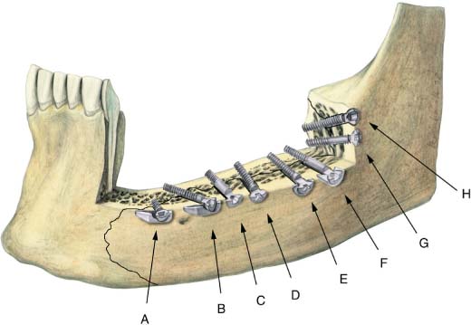
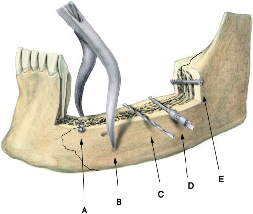
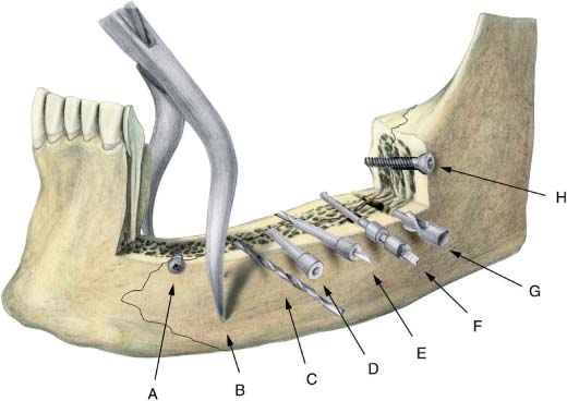
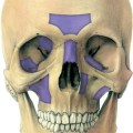
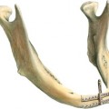
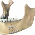
9 Principles of Application of Lag Screws Lag screw osteosynthesis is a form of osteosynthesis in which absolute interfragmentary stability is generated by screws that transfix the fracture gap. The screw is under tension. The screw holes are prepared in such a way that when a screw is tightened, it engages the bone only in the distal fragment—not in the fragment adjacent to the screw head. With a minimum of hardware the lag screw produces interfragmentary stability directly in the center of the fracture line (Fig. 9.1). In contrast, plates apply stability indirectly from the external cortex by tension bending (see Fig. 4.2). The function of a lag screw provides mechanical rest and stability. Therefore, lag screws facilitate direct bone healing (Müller et al., 1991). The Toulouse mini lag screw is a further development within the Champy Titanium Mini Osteosynthesis System (Boutault et al., 1987, 1989). The same instruments and drills may be used for insertion (Fig. 9.2). To understand the concept of a lag screw it is necessary to understand the basic design of the cortical screw, which is the predominant type of screw used in the maxillofacial region (Fig. 9.3). Each cortical screw consists of a head and a shank; the entire length of the shank has threads and defines the screw length. Screw heads come in a variety of configurations; the popular ones have either a straight, cruciform, hexagonal, or square slot (Fig. 9.4). The shank has an internal diameter, also known as the core diameter, and an external diameter or thread diameter. The cortical screw can act as a lag screw only when the hole in the fragment adjacent to the screw head is over-enlarged. This is called the gliding hole. The diameter of the gliding hole is equal to or greater than the thread diameter of the screw. The diameter of the screw hole in the distal fragment is smaller than the gliding hole and corresponds to the core diameter of the screw. The hole in the distal fragment is called the traction hole (Fig. 9.5). Fig. 9.1 Lag screw osteosynthesis produces interfragmentary rest and stability by interfragmentary friction due to the serration of the fragments with a minimum of hardware. Left: a cortical screw as lag screw; right: a typical lag screw. Fig. 9.2 Preparation for a Toulouse mini lag screw in mandibular fracture. (A) Toulouse mini lag screw applied to a lamellar fracture of the outer cortex. (B) Modified towel clip holds the bone fragments in reduction. (C) Bicortical drilling at the internal or core diameter of the screw. (D) Depth gauging. (E) Insertion of a screw resulting in compression of the fracture by bicortical application. Fig. 9.3 Configuration of screws. (A) A cortical screw with a head and a shank. The entire length of the shank has threads and defines the screw length. The shank has an internal diameter, known as the core diameter, and an external or thread diameter. (B) A lag screw. Only the distal part of the screw has threads of the same diameter as the shank in the central part of the screw. (C) A special lag screw (Toulouse mini lag screw). Only the distal part of the screw has threads. The diameter of the shank in all parts of the screw is the same. Fig. 9.4 Screw heads with a variety of configurations from different systems and companies. Top: cruciate and Phillips screw heads. Center: slotted and center drive screw heads. Bottom: special screw heads with cruciate, Phillips, and hexagonal socket heads. Fig. 9.5 Preparation for lag screws in mandibular fracture. (A) Lag screw applied to a lamellar fracture of the outer cortex. (B) Modified towel-clip type of bone holding forceps may be used to hold the bone fragments in reduction. (C) Drilling of a gliding hole in the outer cortex. (D) Insertion of a centering guide in the gliding hole. (E) Use of a centering guide to drill the traction hole coaxially. (F) Depth gauging. (G) Inlet countersinking in the outer cortex. With non self-tapping lag screws, tapping of the traction hole is necessary. (H) Insertion of a screw resulting in compression of the fracture by bicortical application. Fig. 9.6 Configuration of different types of lag screws and washers.
Introduction
Toulouse Mini Lag Screw
Cortical Lag Screw
![]()
Stay updated, free articles. Join our Telegram channel


Full access? Get Clinical Tree


