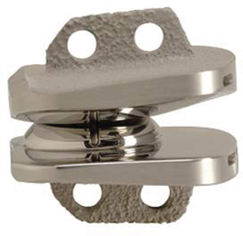
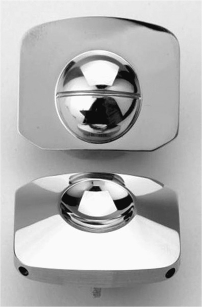
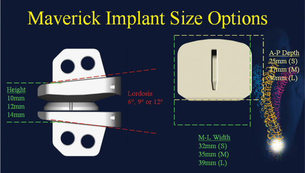
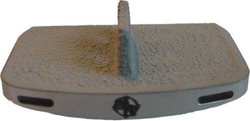
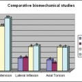
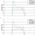
24 Hydroxyapatite Coating Fixation Streamlined Surgical Technique Oswestry Disability Questionnaire Scores The current standard of care for the treatment of lumbar degenerative disk disease is spinal fusion. Spinal fusion is designed to increase stability of a diseased motion segment, while necessarily limiting motion. This static stabilization, however, is coming under increased scrutiny as a potential contributor to adjacent level degenerative changes, even as improved materials and surgical techniques drive very high rates of successful fusion.1–3 Clinical outcomes following fusion may likewise be problematic in that painful loading across the disk space may still occur.4,5 In response to these apparent shortcomings, it has been proposed that motion stabilization via disk arthroplasty, rather than disk arthrodesis, may be a preferred treatment.6–9 The two most clinically notable designs in use in the world today, the SB Charité III (DePuy Spine, Raynham, MA) and the ProDisc (Synthes, Inc., West Chester, PA), are both based on articulating cobalt-chromium-molybdenum (CoCrMo) on ultra high molecular weight polyethylene (UHMWPE). The earliest versions of the SB Charité have been in use since ~1984, with the current model III design in use since ~1987. Both Charité10–13 and ProDisc14 have been used with some reported clinical success. Maverick Total Disc Replacement (TDR) (Medtronic Sofamor Danek, Inc., Memphis, TN) is among the next generation of arthroplasty implants and is intended for use in the lumbar spine to treat degenerative disk disease.8,15 The Maverick TDR was certified for implantation in Europe in 2001 and was first applied clinically in the United States in April 2003. Maverick TDR has already undergone an extensive evaluation of material and design strength, durability, wear, and surgical implantation techniques.8,15–17 The unique design characteristics of the Maverick prosthesis allow for improved function with superior wear via a metal-on-metal (MOM) articulation in a ball and socket joint (Fig. 24–1). Similar to the experience in total hip prostheses, it is expected that using CoCrMo alloy for both articulating surfaces will provide excellent wear characteristics.18–21 The Maverick TDR consists of male and female, MOM end plates (Fig. 24–2). The male end plate is intended for positioning on the superior end plate of the inferior vertebra at the treated spinal level. The device is manufactured from cobalt-chromium-molybdenum (CoCrMo). The bone-abutting surface is chemically textured to provide a roughened surface geometry and is subsequently coated with hydroxyapatite (HA) by a thermal plasma-spray deposition process. Protruding from the bone-abutting surface is a keel, which provides for device stability by press-fitting into a prepared channel in the vertebral body. The articulating surface has a male (convex) dome, which mates with the female end plate. The male end plate is available in only one height. The female end plate is identical to the male end plate except that, instead of a convex male dome, it has the mating concave female receiving surface and is offered in several heights. The mated device allows for 16 degrees of motion off the neutral position in all bending directions. Both male and female end plates may be preangled either 3 degrees or 6 degrees. Both end plates are offered in small, medium, and large sizes. All joints are designed to be interchangeable. Therefore, the surgeon is able to interchange components to build a wide configuration of constructs. Some examples include 6 degrees, 9 degrees, or 12 degrees of prelordosis as well as posterior heights of 10 to 14 mm, and may even include a combination of different footprint sizes (Fig. 24–3). For example, a small female end plate could be mated with a medium male end plate. Figure 24–1 MAVERICK Total Disc Replacement two-piece ball and joint prosthesis. A thorough analysis and understanding of the biomechanical properties of spinal segments is a critical prerequisite in the design of prosthetics for disk arthroplasty.4,7–9,16,17,22 Consideration must be given as well to the intended patient population, for whom longevity may be a significant requirement of the motion-preservation device. The Maverick TDR is designed as a permanent implant, intended to maintain segmental motion at the affected level. Testing involved material and design issues such as shear and compressive strength, long-term durability, wear performance, and shock absorption. Furthermore, strategic surgical considerations such as implantation technique8,16,17,22 were optimized. Several key elements were ultimately incorporated in this design in pursuit of optimal motion stabilization: The Maverick prosthesis possesses a fixed center of rotation (COR) in the posterior third of the device. Accurate placement of any TDR prosthesis is critical to preserve normal motion and reduce facet loads. Extreme posterior placement of any prosthesis is often difficult. In a ball and cup design, facet loads are sensitive to COR location. Placement of a prosthesis too far anterior is felt to magnify facet loading over 2.5 times normal,8 which may lead to early degeneration and continued pain. By having the COR posterior within the device itself, Maverick allows “forgiveness” of any surgical placement that is less than optimal (Fig. 24–4). In addition, this design provides up to 3 mm of controlled translation while mimicking the normal kinematics of the spine. Among the benefits of MOM design is longer survivorship.23 The track record of UHMWPE wear in large joint replacement is well reported.24,25 Given the fact that any anterior revision of a TDR could be life threatening, the optimal prosthesis should be able to last the patient’s lifetime. Wear debris from polyethylene can be associated with osteolysis and foreign body reaction. For that reason, the use of MOM for reduced wear in spinal applications was one of the critical Maverick design considerations. CoCrMo alloy, currently used in large-joint total arthroplasty, may provide the opportunity for long-lasting utilization without the complications of conventional polyethylene wear debris.23–26 In hip replacement, MOM produces up to two orders of magnitude less wear than metal-on-conventional UHMWPE hip prostheses.27 Use of a MOM prosthesis in the spine appears to be more advantageous than in the hip due to the different forces generated from this anatomical location.8 Figure 24–2 Maverick metal-on-metal end plates (cobalt-chromium-molybdenum alloy). Wear testing of Maverick demonstrated low wear of ~14 mm3 during the 10 million cycle (MC) duration of the test. Assuming that there are 125,000 significant bends in 1 year in situ, this equates to 14 mm3 of wear over ~31.5 years of use or 0.35 mm3/year. Compared with in vitro simulator wear tests of MOM hip implants, which exhibit wear rates of ~0.38 mm3/MC,18–20 or 0.38 mm3/year with the assumption that the average hip arthroplasty patient takes 1 million steps per year, the wear of Maverick is well within that reported for MOM hips in current clinical use. It is interesting to note that the annualized wear rate of Maverick is further reduced to 0.14 mm3/year with the assumption of 125,000 bends per year as used by Dooris et al.28 Finally, because all in vitro testing must be validated through comparisons with explanted devices, it is noteworthy that the Maverick was the subject of such a comparison in only the published studies comparing simulator-tested and retrieved implants of the same type.29,30 These studies compared in vitro–tested Maverick implants to an explanted Maverick device and found marked differences between the surface morphology of the articulating surfaces. In general, the simulator-tested implants showed highly visible wear scars, whereas the surface of the explanted device was highly polished with minimal scratching. This strongly suggests that the in vitro simulator test conditions are harsher than what occurs physiologically. Therefore, the wear rates generated in simulator testing may overestimate the actual in situ wear of the implants. The main perceived objection to MOM designs is the increased systemic exposure to metal ions due to metal wear debris. In a study where CoCrMo particles were administered to the spine in a rabbit model,31 CoCrMo wear debris particles were calculated for dosage levels equivalent to 10-year, 30-year, and 60-year exposure after CoCrMo-onCoCrMo TDR. Intervertebral injection sites at L5 or L6, local lymph nodes adjacent to the implantation site, and distant lymph nodes were evaluated microscopically in both investigational and control animals. In addition, liver, kidneys, spleen, and thymus of all animals were assessed microscopically. The results of this study simulating up to 60 years of clinical use of a CoCrMo-on-CoCrMo device indicated no significant histological changes when comparing treated and control animals. Human studies are now ongoing to look at the production of ions associated with MOM designs. Figure 24–3 Maverick Total Disc Replacement interchangeable components provide flexibility to build a wide range of constructs. Figure 24–4 Posterior center of rotation corresponds more closely to patient anatomy. Used in arthroplasty for 30 years, this osseoconductive synthetic-bone material is highly crystalline, providing an excellent bone-device fixation surface. In addition, the roughened Chemtex surface (Fig. 24–5) provides increased friction for a press fit. This final element of the design rationale provides the surgeon with a complete tray for en bloc diskectomy, with the All-in-1 guide (provided in the Maverick kit) (Fig. 24–6A–C) for accuracy and reproducibility. The All-in-1 guide maintains lordosis, measures anteroposterior depth, measures height distraction, and guides chiseling. In conjunction with proper sizing, this guide promotes surgical efficiency and device effectiveness for optimal results.
MAVERICK Total Disc Replacement
 Male End Plate (Inferior Component)
 Female End Plate (Superior Component)
 Design Rationale of the Maverick
Male End Plate (Inferior Component)
Female End Plate (Superior Component)
Design Rationale of the Maverick
Posterior Center of Rotation
Metal-on-Metal Design
Hydroxyapatite Coating Fixation
Streamlined Surgical Technique
 Patient Selection
 Surgical Technique
 Clinical Outcomes
 Conclusion
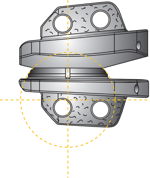
Related posts:
 Prosthetic Disk Nucleus Partial Disk Replacement: Pathobiological and Biomechanical Rationale for Design and Function
 Complications of Lumbar Disk Arthroplasty
 Tension Band System
 Cervidisc Concept, Six Years Follow-Up and Introducing Cervidisc II: DISCOVERY
 Rationale for Dynamic Stabilization
Stay updated, free articles. Join our Telegram channel

Full access? Get Clinical Tree


