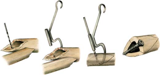
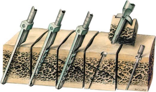
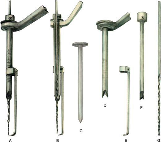
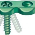
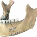
10 Guided Lag Screw Technique in Mandibular Fractures Under certain conditions the application of a lag screw can be difficult in mandibular fractures, and the direction and position of screws are not always predictable by the conventional lag screw technique. The drill guide developed for extremity traumatology (Müller, Allgöwer, and Willenegger, 1969; Müller et al., 1991) is not practicable in mandibular fractures (Fig. 10.1). For this reason special instruments for guidance of lag screws have been developed, to enable fractures of the mandible to be accessed and fixed through a transoral approach, by the guided lag screw technique (Chotkowski, 1997). The exceptions to a transoral approach are: • severely atrophied mandibles • severely comminuted fractures • fractures of the condyle and high condylar neck The guided lag screw technique utilizes precision instrumentation together with a specialized screw for the fixation of mandibular fractures (Fig. 10.2). It provides a predictable method of rigid internal fixation with minimal hardware through the use of conservative surgical access in a short operative time (Ellis and Ghali, 1991). Fig. 10.1 Drill guide for lag screw technique in extremities. Application for tibia fracture. Fig. 10.2 Application of the screw and use of the drill guide. The under-surface of the head of the screw has a biconcave bevel. When the screw is tightened, it directs the compressive forces to the smooth surface of the shaft of the screw. This increases the overall frictional forces of the screw with the bone which, in turn, increase the total compressive forces across the fracture (see also Fig. 9.7, E). Fig. 10.3 Equipment for the guided lag screw technique. Drill guide, pointer, adjustable countersink and stepped drill bit (A), cross-section (B), trocar (C), calibrated drill guide with beveled end (D), adjustable calibrated pointer (E), adjustable biconcave beveled countersink (F), stepped drill bit (G). The biomechanics of the mandible give the best preconditions for lag screw application (Rudderman and Mullen, 1992). The guided lag screw technique differs from conventional lag screw techniques in that it eliminates uncertainties and reduces the number of operative steps (Fig. 10.3). The drill guide enables the surgeon to adjust the drill bit so that its point of exit can be predicted accurately. This ensures that anatomical structures, roots of teeth and their associated neurovascular bundles will be avoided when drilling. The pointer, which functions as an external depth gauge, runs parallel to the direction of the drill bit and measures the length so that the proper guided lag screw can be selected. Surgical time is also decreased with the use of the stepped drill bit and adjustable countersink. The stepped drill bit tapers from 2.3 mm to 1.7mm. The countersink, gliding, and pilot holes can be prepared in one pass. This reduces the risk of misalignment of the holes, which can occur when multiple drill bits are passed. The most important aspect of fracture management is to reproduce the occlusion that existed before the injury. The occlusion may be secured by using intermaxillary arch bars, Ernst ligatures, Ivy loops, or temporary intermaxillary fixation screws with interarch wires.
Introduction
The Surgical Technique
Stabilization of the Occlusion
Surgical Approach
Related posts:
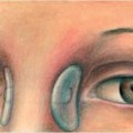
 Sublingual Hematoma: Pathognomic of Fracture of the Mandible
 Materials and Instrumentation
 Application of Resorbable Plates, Screws and Pins for the Treatment of Midface and Condylar Neck Fractures, and Correction of Craniosynostoses
 Orthognathic Surgery Distance Screws
 Naso-ethmoid Fractures
 Mandibular Fractures Including Atrophied Mandible
Stay updated, free articles. Join our Telegram channel

Full access? Get Clinical Tree


