CHAPTER 60 Computerized Hip Navigation
Computerized navigation in the field of total joint arthroplasty is a relatively new tool that is gaining acceptance among orthopedic surgeons internationally. This tool has been able to be introduced into orthopedic operating rooms owing to the increased performance and decreased size of personal computers as well as the development of accurate infrared stereoscopic cameras. The use of navigation as an aid to total knee arthroplasty has become quite commonplace, with a number of studies reporting that better and more consistent mechanical alignment is achievable using navigation as compared with conventional mechanical alignment jigs.1 The introduction of navigation as an aid to total hip arthroplasty has been somewhat slower because of the added complexity of factors such as patient registration and the increased functional requirements of the system. The lack of a consistent identifiable target position in which to place the acetabular and femoral components further complicates the issue.
Accurate assessment of component placement in total hip replacement is difficult. Traditionally, standardized plane x-ray studies have been used to measure acetabular component position and femoral component position.2 Unfortunately, none of the radiologic measures have validated clinical accuracy for component position, particularly with respect to difficult measurements such as cup and stem version. It is important to bear this in mind when assessing the value of hip navigation systems that give parameters to the nearest degree.
However, along with the development of the different navigation systems, CT planning software packages have become increasingly sophisticated. Although designed for positioning virtual implants in the axial, coronal, sagittal, and three-dimensional reconstructed views of a hip CT scan, they work equally well as an accurate way of measuring the position of implanted components.3 The appropriate-sized virtual templates are simply laid over the acetabular component or stem. The values for cup inclination, cup version, stem version, stem flexion, and stem varus are then simply presented by the computer.
Saxler and colleagues4 reviewed 105 patients who had undergone total hip replacement with freehand insertion of the components. They all underwent postoperative CT scanning; the scans were analyzed by using the hip planning module of the SurgiGATE-System (Medivision, Oberdorf, Switzerland). They studied the acetabular components and found that the mean inclination angle was 45.8 degrees ± 10.1 degrees and the mean anteversion angle was 27.3 degrees ± 15.0 degrees. What constitutes good component position has been discussed in earlier chapters, but in this study the researchers concluded that only 27 patients had an acetabular component that was within the so-called safe zone of Lewinnek.5 More importantly, this paper demonstrated just how extreme the outliers can be, with acetabular component version ranging from 23.5 degrees to 59.0 degrees and inclination ranging from 23.0 degrees to 71.5 degrees. For navigation to be a benefit, the system must offer the ability to provide a target position for component placement as well as to eliminate these outliers.
THEORY
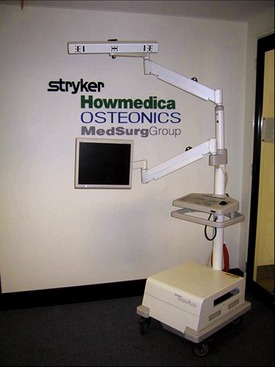
Imageless hip navigation systems require no preoperative or intraoperative scanning or fluoroscopy apart from the plain radiographs that would be performed by all surgeons before any hip arthroplasty procedure. At the time of surgery, a fixed body with a tracker attachment post is attached to the iliac wing and the distal femur on the appropriate side for surgery. As before, these trackers are critical to the procedure, with all subsequent component positioning referenced to these fixed points. They can either be passive, reflective arrays, picked up by the computer’s overhead infrared sensor, or independent, active microprocessors that send signals to an overhead camera (Fig. 60-1).
The experience of this unit is with active trackers. Users of passive trackers have occasionally had problems with blood on the trackers obscuring the reflection of the infrared camera signal. The sensor or camera is connected by a small gantry to the navigation computer and screen, which is a contained, mobile unit (see Fig. 60-1).
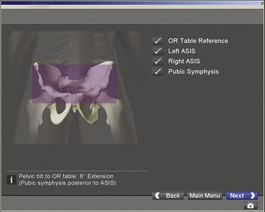
The anterior pelvic reference frame is defined by a pointer with an integral tracker, as discussed (Fig. 60-2).

FIGURE 60-2 Screenshot showing anterior pelvic plane, which is defined by both anterior superior iliac spines.
EVIDENCE
Several studies evaluating CT-based navigation systems have been performed. Jolles, Genoud, and Hoffmeyer6 recruited 10 surgeons to each perform 15 trial insertions of an uncemented cup into a plastic bone and foam model using standard mechanical guides and the CT-dependent Medivision system (Medivision, Oberdorf, Switzerland). The results were highly significant, with a 60% reduction in maximum error and a 50% reduction in mean error for both cup inclination and version. Widmer and Grutzner7 evaluated 14 hip replacements performed by two surgeons using a CT-dependent navigation setup (SurgiGATE, Medivision, Oberdorf, Switzerland). In this small study, cup position was optimized (i.e., the range of values for cup inclination and version was significantly narrowed). Leenders and colleagues8 also showed that CT-based navigation improved accuracy of cup position in a control study of 150 hips, with a significant decrease in the variability of cup position for both inclination and version.
Fluoroscopic navigation techniques have also shown promising results. Grutzner and colleagues9 performed 236 consecutive hip replacements using fluoroscopic images linked to navigated pelvic registration. In the first 50 cases, acetabular position was evaluated using the CT planning software. The mean inclination was 42 degrees (37 to 49 degrees), and the mean version was 21 degrees (10 to 28 degrees). The difference between intraoperatively calculated cup position and postoperatively measured implant position was 1.5 degrees (standard deviation [SD] 1.1 degrees) for inclination and 2.4 degrees (SD 1.3 degrees) for anteversion. Zheng and colleagues10 also assessed the same fluoroscopic navigation technique in 10 cases. The numbers were small, but in addition to acetabular navigation, the femoral component was also navigated with respect to offset, version, varus-valgus alignment, and leg length. In eight cases, surgeons were satisfied with the femoral component position guided by the navigation. In two cases the navigation had to be abandoned because of technical problems.
However, the results now appearing with imageless computer navigation are most relevant, as there is a general shift toward this most recently developed form of hip navigation. Nogler and colleagues11 used the Stryker Hip Navigation System (Stryker Leibinger, Freiburg, Germany). Bilateral acetabular cup insertion was carried out in 12 human cadavers through an anterolateral transgluteal approach using a press-fit, uncemented cup. One side was navigated and the other side was a control. The median position for median inclination and median version were similar for both groups, but the 90th percentile range was 15.7 degrees and 18.5 degrees, respectively, for inclination and version in the control group, compared with 4.3 degrees and 7.1 degrees in the navigated group. Kiefer12 performed 156 cementless total hip replacements with cup placement guided by the OrthoPilot hip navigation system (B. Braun Aesculap, Tuttlingen, Germany). Postoperative cup position was measured on plane x-ray images, with Pradhan’s technique used to calculate cup version.2 The mean inclination angle given by the computer at cup insertion was 41 degrees (SD 5 degrees) and was 42 degrees (SD 5 degrees) for the inclination measured on x-ray films. Cup version was less accurate, with a mean version at cup insertion of 15.9 degrees (SD 4.5 degrees) and of 10.9 degrees (SD 4.8 degrees) on postoperative radiologic assessment. Wixson and colleagues13 performed a consecutive series of 82 hips navigated using the Stryker Leibinger Hip Navigation System (Stryker Leibinger, Freiberg, Germany) and compared postoperative cup position with positions from a cohort of 50 standard hip replacements, using digitized x-ray studies. The target range for cup inclination was 40 to 45 degrees and the target range for anteversion was 17 to 23 cases. Only six of the control cases were in the target range, compared with 30 of the navigated cases, a highly significant difference (P < .001).
Most of the studies presented have focused on acetabular component positioning, and there have been weaknesses in all cases. The limitations of postoperative radiographic assessment with plane x-ray studies, a method used in some of the studies mentioned in the previous paragraphs, were alluded to earlier. Lack of a control group or adequate statistics lowers the value of others. Perhaps most important of all is what implant positions are considered optimal. Many of the papers published make reference to Lewinnek’s guide to optimal cup position. This was a retrospective study on small numbers using plane x-ray images to measure cup position.5
We have been prospectively evaluating the outcomes of the Stryker Hip Navigation System (Stryker Leibinger, Freiberg, Germany) as part of a randomized control trial.14 Postoperative cup and stem position is measured on high-definition postoperative CT scans using the Stryker CT Hip Navigation software for accurate three-dimensional measurement of both acetabular and femoral component positions. We have found this system to have very good accuracy, with low intraobserver and interobserver error. The aim of the study has been to demonstrate the accuracy of hip navigation—that is, how well the position for an implanted component indicated by the hip navigation system relates to the postoperative position. For control hips we asked the operating surgeons to estimate the position they thought they had achieved, and related this to the postoperative three-dimensional CT measurement. We have performed 80 total hip replacements, with navigation used in 39 cases. In the navigated group, two subgroups were studied; in one group, pelvic registration was performed with the patient supine before positioning, and in the other group, registration was performed after the patient was prepared and draped in the lateral position. Both techniques were assessed for accuracy. Forty-two hips were uncemented, and 38 were cemented. There was no difference between the groups with regard to pathology, age, sex, body mass index, or type of implant. The difference between predicted and postoperative position was normally distributed for both the navigated and the control groups. The range of values was significantly narrowed in the navigation group for cup inclination (P < .05), cup version (P < .05), and stem version (P < .05).
As shown in Figure 60-3, in our hands registration in the supine position was more accurate than registration in the lateral position. Registration in the lateral position was still significantly more accurate than in the control cases. There was one infected hip in the control group and a single dislocation in both groups.
Stay updated, free articles. Join our Telegram channel

Full access? Get Clinical Tree


