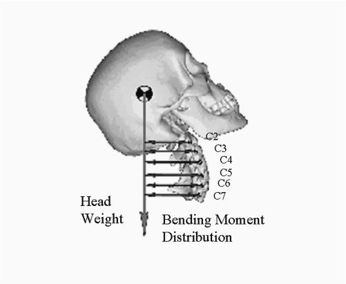
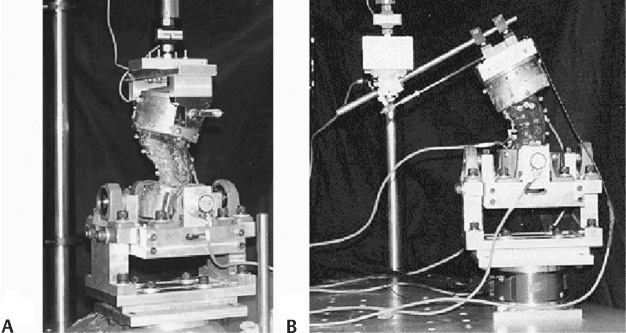
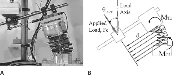
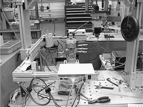
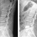
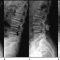
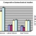
4 Specimen Preparation and Spine Conditions Nondestructive Testing Criteria Pinned-Pinned and Pinned-Fixed Mounting Conditions Modified TPF Mounting Condition Displacement versus Load Control Information used to assess the performance of spinal instrumentation or surgical techniques can come from mechanical or fatigue tests, computational studies, animal studies, in vitro studies, and clinical trials. With regard to in vitro studies, biomechanical testing on human cadaveric tissue offers a practical means for evaluating and ranking different surgical instrumentation and techniques. However, there are currently no standard tissue-based testing protocols for evaluating spinal devices. Although a variety of different testing methods have been used to study cervical spine mechanics, most testing protocols were developed to study fusion instrumentation and may not be suitable for disk arthroplasty. The most suitable method for evaluating these mobile spinal devices in vitro remains unclear.1–4 Additionally, the different basic control strategies that have been used with the two most common methods are load control and displacement control.2 Under load control, a pure or constant moment is typically applied to the spine in one plane of motion at a time (i.e., sagittal, frontal, or transverse). Under displacement control, the translational and rotation motions of the vertebrae are controlled. The cervical spine consists of a series of free vertebral bodies that exhibit complex, coupled motions and loading behaviors.5 For in vitro testing, the spinal bodies must be analyzed based on the motion/load conditions that are prescribed and applied by the testing device. The motions of interior spinal bodies not in direct contact with the testing device are measured but cannot be controlled. For the subaxial cervical spine, in vivo motion is greatest in the sagittal plane, with more rotation occurring in extension than in flexion.5 Only small amounts of muscle activity are needed to maintain the head’s orientation in an erect neutral position. Thus muscleinduced compression is small, and head weight is the typical physiological force that acts on the cervical spine. Flexion or extension of the head induces a bending-moment distribution throughout the cervical spine that increases caudally and acts in combination with the compressive (head weight) force (Fig. 4–1). In vitro testing methods should replicate this bending moment distribution. This chapter reviews different methods for testing the cervical spine in vitro in an attempt to identify the appropriate loading conditions that would replicate the in vivo motion response, and to help determine the most suitable method for evaluating disk arthroplasty or motion preservation devices in vitro. Simple mechanical devices continue to be used that incrementally apply pure static moments to the spine.6 More commonly, however, programmable testing systems are used. Smith et al7 used a material testing system (MTS) machine to study spine mechanics; the mounted specimen was highly constrained (no motion was permitted above or below the area of interest) and did not replicate physiological motion or loading conditions. Owing to the relatively few degrees of freedom available with standard materials testing machines, custom fixtures must often be added to permit suitable movements, which often remain limited to simple scenarios (i.e., tension-compression, pure torsion, four-point bending). Figure 4–1 In vivo sagittal motion and mechanics of the cervical spine. This illustration depicts the caudally increasing bending moment distribution in the cervical spine (2–5 Nm), greatest at the C5–C6 level, created by continuous rotations with like polarity at each vertebral level (40 degree flexion or extension) with an axial compressive load (50 N head weight).3,16,20,28 Weinhoffer et al8 added a slotted plate fixture to an MTS actuator to enable spinal rotation with nonvertical translation. As the actuator moved down, the upper pot attachment was free to rotate but was constrained to follow a slotted path. The orientation of the slot imposed a specific horizontal versus vertical translational relationship of the upper spinal body that, in turn, was nonphysiological. Kunz et al9 modified a 2 degree of freedom (DOF) MTS machine by adding a third rotational DOF to the base of the device. The device was used for pure moment testing with or without an axial compressive load. James et al10 presented a 2 DOF spine tester that regulated axial rotation with either flexion-extension or lateral bending. Independent control of each motor prevented force feedback or force limit control features. Shea et al11 developed a 3 DOF testing apparatus for planar analysis of spine biomechanics that provided independent control of the displacement output of each axis, but no force feedback control schemes were provided. Figure 4–2 End mounting configurations. (A) The pinned-pinned or pinned-fixed configuration and (B) translational/pinned-fix configurations. Wilke et al4 developed a spine tester that applied pure moments to the superior end of a spinal construct in three orthogonal directions through the use of counterbalanced stepper motor units attached to the superior end of a spinal construct. The testing protocol was limited to pure-moment loads only. More recently, Gilbertson et al3 employed robotics technology to study single motion segment unit (MSU) lumbar spine mechanics. Extensive modifications to the manipulator itself (at significant expense) were required and in the end the test system was limited to quasi-static analysis or pure-moment load control schemes. An improved testing protocol has been developed that used a programmable single actuator biomechanical testing apparatus.12–14 The rigid frame housed a servo driven load actuator (Industrial Device Corp., Novato, CA) commanded by a robotic controller (Adept Inc., San Jose, CA). A single-axis load cell (Transducer Technologies, Temecula, CA) was in line with the shaft of the load actuator. The other end of the load cell was coupled to end mounting fixtures that regulated the end motion and loads applied to the spinal construct. The opposing end of the construct was coupled to a six-axis force sensor (JR3 Inc., Woodland, CA), which was in turn rigidly fixed to the base of the test frame. The multiaxis load cell reported the three orthogonal forces and moments transferred through the spine in real time. With this modified approach, displacement of the spine was controlled and a “bending moment distribution” was induced throughout the spine via custom fixturing hardware. Other parameters were monitored to establish the upper motion limit and the total applied moments and end loads. By assigning a limit value to each parameter, the test was stopped if any limit checks were exceeded. This arrangement is vastly different from and superior to pure-moment methods where there is no limit check on the resultant global motion. Further, cervical spine studies using pure-moment protocols typically use moment values in the range of 1 to 2 Nm. However, when analyzing cervical spine instrumentation, this load level may not be sufficient to induce measurable differences in the motion response. This modified testing system was used to simulate the different end mounting configurations. Figure 4–3 (A) Photograph of a subaxial cervical spine mounted in the testing apparatus. (B) Schematic of mounted specimen. With the flexion-extension axis of the spine placed eccentric to the load axis of the actuator, a compressive load (Fc) and flexion-extension bending moment (Mf/e, where Mf/e = Fc * d) were induced. A sequence of tests was performed to analyze different end mounting configurations and appropriate ranges of load and motion to identify a particular set of end conditions that reproduced normal motion of the multibody spine.13 The gold standard of motion was replication of positions considered normal by anatomists, physical therapists, and spine surgeons. Three different mounting configurations were evaluated: pinned-pinned (PP), pinned-fixed (PF), and translational/pinned-fixed (TPF) (Fig. 4–2). In the first test condition, the lower mounting fixtures were unclamped and free to rotate, whereas in the second condition they remained fixed. The upper mounting fixtures converted the single-controlled linear input from the load actuator to either a rotational motion or pure bending moment input alone (PP and PF condition), or to a coupled motion input (unconstrained translations and/or rotation in the sagittal plane) with a combined loading state of axial compressive force alone or with a flexion-extension bending moment (TPF configuration). Figure 4–4 Lateral bending testing arrangement. For the TPF case, the upper fixturing hardware consisted of a linear bearing and splined shaft assembly that mounted in a rotating joint attached to the actuator (Fig. 4–3). The linear bearing provided a virtually frictionless method for the splined shaft to move relative to the actuator, effectively eliminating the shearing forces. The flexion-extension axis of the spine was placed eccentric to the load axis of the actuator and induced a compressive load (Fc) and flexion-extension bending moment to the upper pot (MT1). The specimens were mounted in an inverted neutral orientation with the T1 pot attached to the upper fixture and the C2 pot mounted to the lower base fixture, thereby inducing a greater moment at T1 than at C2 (Fig. 4–3B). Specimens with gross alignment deformities were not used.
Biomechanical Testing Protocol for
Evaluating Cervical Disk Arthroplasty
 Tissue-Based Biomechanical Studies
 Review of Biomechanical Testing Systems
Tissue-Based Biomechanical Studies
Cervical Spine Mechanics
Review of Biomechanical Testing Systems
Improved Testing Protocol
End Mounting Configurations
 Cervical Spine Mechanics
 Improved Testing Protocol
 Results
 Discussion
 Conclusion
 Sources of Support
Related posts:
 Prosthetic Disk Nucleus Partial Disk Replacement: Pathobiological and Biomechanical Rationale for Design and Function
 Complications of Lumbar Disk Arthroplasty
 Tension Band System
 Cervidisc Concept, Six Years Follow-Up and Introducing Cervidisc II: DISCOVERY
 DIAM (Device for Intervertebral Assisted Motion) Spinal Stabilization System
Stay updated, free articles. Join our Telegram channel

Full access? Get Clinical Tree


