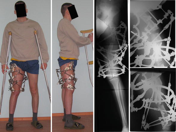
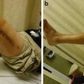
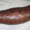
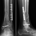
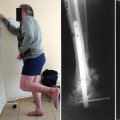
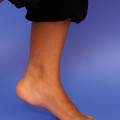
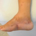
Fig. 1
(a, b) Pre-operative clinical pictures and (c, d) radiographs of the right femur
3 Preoperative Problem List
(a)
Complex six-component, three-planar two-level deformity of right femur: right MAD = 14 mm lateral; mLPFA = 75 deg.; mLDFA = 85 deg.; mMPTA = 88 deg.; mLDTA = 91 deg.
(b)
Shortening of the right femur = 4 cm.
4 Treatment Strategy
We chose to perform a two-level correction at each apex of deformity. In addition, gradual lengthening will correct the shortening. The deformity correction was performed using the computer-assisted Ortho-SUV frame.
5 Basic Principles
(a)
Use of external fixation provides possibility of simultaneous gradual lengthening and deformity correction.
(b)
Use of computer-assisted Ortho-SUV frame provides precise, one-step gradual deformity correction.
(c)
Two-level deformity is better to correct from two osteotomies made at each center of rotation of angulation (CORA). This may not always be technically possible. If a multilevel deformity is corrected through a resultant CORA, the regenerate will be curved.
(d)
The osteotomies should be made from small incisions not exceeding 1 cm.
(e)
Use of module transformation of the circular external frame is made in response with callosity formation and decreases the bulkiness of the frame.
6 Images During Treatment
See Figs. 2, 3, 4, 5, 6, and 7.
Get Clinical Tree app for offline access
Fig. 2
Clinical pictures and radiographs after surgery: Ortho-SUV frame (two sets of Ortho-SUV frame) is applied and two-level osteotomy of the right femur has been performed
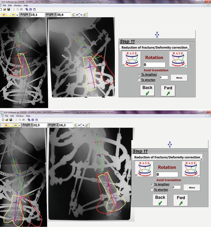
Fig. 3
The Ortho-SUV software window at step 11: planning of deformity correction at the levels of both osteotomies. The bone fragments anatomical axes are drawn. Yellow
 8: Femoral Bone Defect
 28: Proximal Tibial Bone Defect Treated with Intentional Deformity and Bone Transport
 30: C3.3 Pilon Fracture Closed. Ilizarov Fixation with Limited Open Reduction of Joint Surface and Distal Tibia Bridging Distraction of Ankle Joint
 78: Two-Stage Treatment of a Chronic Foot Dislocation
 84: Lapidus Fusion with External Fixation
 65: Closed Correction of Club Foot with Ilizarov


Related posts:
8: Femoral Bone Defect
28: Proximal Tibial Bone Defect Treated with Intentional Deformity and Bone Transport
30: C3.3 Pilon Fracture Closed. Ilizarov Fixation with Limited Open Reduction of Joint Surface and Distal Tibia Bridging Distraction of Ankle Joint
78: Two-Stage Treatment of a Chronic Foot Dislocation
84: Lapidus Fusion with External Fixation
65: Closed Correction of Club Foot with Ilizarov
Stay updated, free articles. Join our Telegram channel
Full access? Get Clinical Tree
